


Groundsmaster 3505--DPage 5 -- 14Electrical System
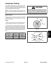
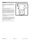
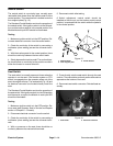
Neutral Switch
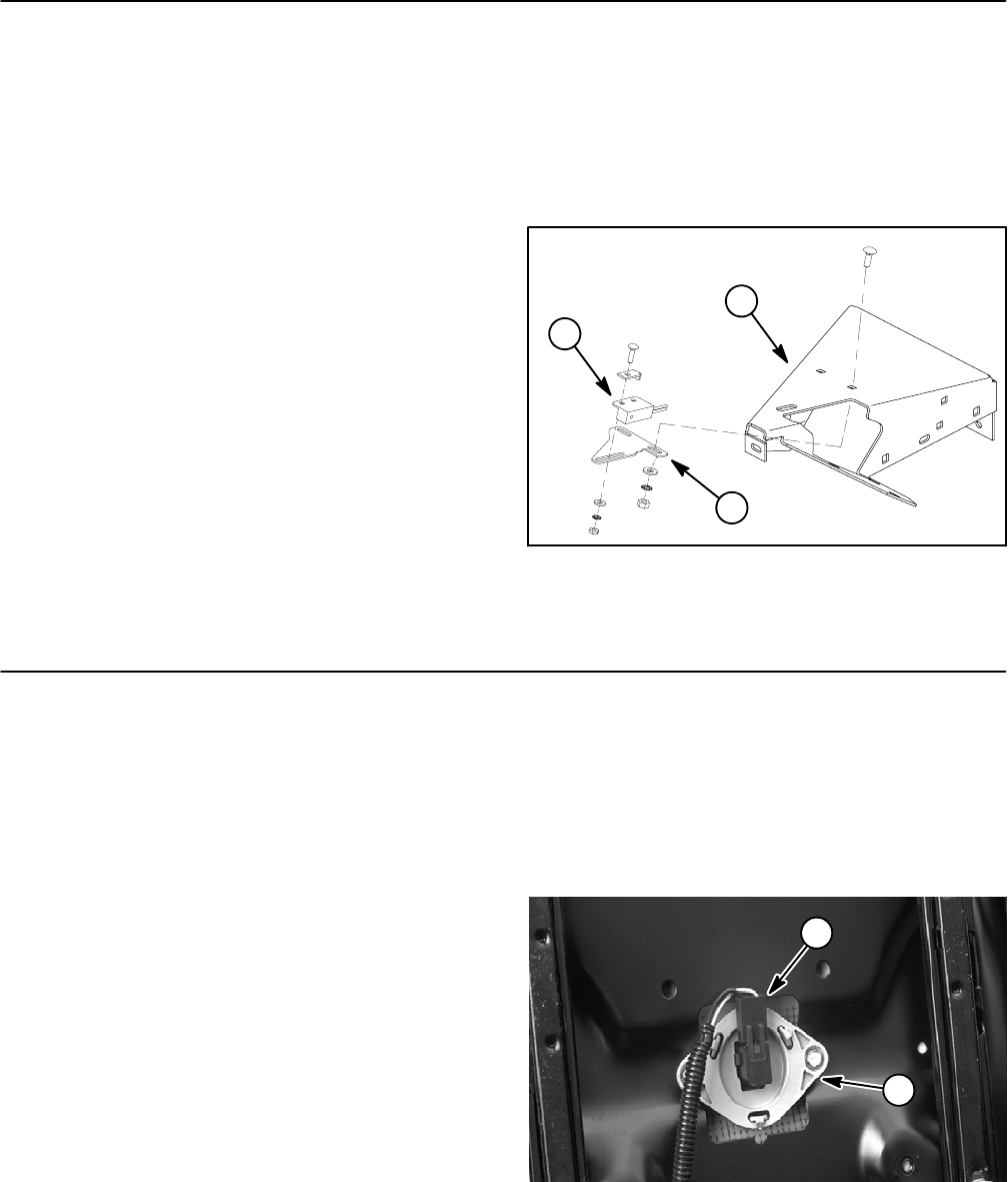
The neutral switch is a proximity type, normally open
reed switch that closes when the traction pedal is in the
neutral position. The neutral switch is located under the
floor support plate (Fig. 15).
The Standard Control Module monitors the operation of
the neutral switch. If the ignition switch is in the ON posi-
tion and the traction pedal is in the neutral position, the
Module Neutral input LED should be illuminated.
Testing
1. Make sure ignition switch is in the OFF position. Dis-
connect electrical connector from the neutral switch.
2. Check the continuity of the switch by connecting a
multimeter (ohms setting) across the connector termi-
nals.
3. With the traction pedal in the neutral position, there
should be continuity between the two switch leads.
4. Slowlydepress the tractionpedal. Thecontinuity tes-
ter should show no continuity as the pedal is moved in
either the forward or reverse direction.
5. Reconnect switch after testing.
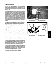
6. Switch adjustment: neutral switch should be
installed so that the pin on the traction pedal (neutral
position) is centered with the switch when the pedal is
in the neutral position.
1. Neutral switch
2. Floor support plate
3. Switch bracket
Figure 15
2
1
3
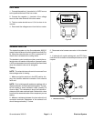
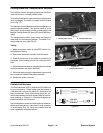
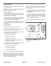
Seat Switch
The seat switch is normally open and closes when the
operator is on the seat. If the traction system or PTO
switch is engaged when the operator raises out of the
seat, the engine will stop. The seat switch (Fig. 16) and
its electrical connector are located directly under the
seat.
The Standard Control Module monitors the operation of
the seat switch. If the ignition switch is in the ON position
and the seat is occupied, the Module in seat input LED
should be illuminated.
Testing
1. Make sure ignition switch is in the OFF position. Re-
move seat (see Operator Seat in Service and Repairs
section of Chapter 6 -- Chassis).
2. Disconnect electrical connector from the switch.
3. Check the continuity of the switch by connecting a
multimeter (ohms setting) across the connector termi-
nals.
4. With no pressure on the seat, there should be no
continuity between the seat switch terminals.
5. Press directly onto the seat switch through the seat
cushion. There should be continuity as the seat cushion
approaches the bottom of its travel.
6. Reconnect seat switch connector. Reinstall seat as-
sembly.
1. Seat switch 2. Electrical connector
Figure 16
2
1