


Groundsmaster 3505--D Hydraulic SystemPage 4 -- 81
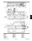
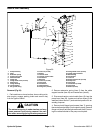
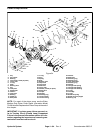
Piston Pump Removal (Fig. 51)
1. Park machine on a level surface, lower cutting units,
stop engine, engage parking brake and remove key
from the ignition switch.
2. Remove traction belt from the pulley (see Traction
Unit Operator’s Manual).
3. Remove neutral arm assembly from the piston pump
(see Neutral Arm Assembly Removal in this section).
4. Drain hydraulic oil from Hydraulic tank (see Traction
Unit Operator’s Manual).
5. Thoroughly clean hydraulichose ends and fittingson
piston pumpto preventhydraulic system contamination.
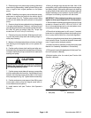
WARNING
Before disconnecting or performing any work
on the hydraulic system, all pressure in the
system must be relieved. See Relieving Hy-
draulic System Pressure in the General Infor -
mation section.
6. Label all hydraulic hoses and fittings for assembly
purposes.
7. Disconnect all hydraulic hoses connected to the hy-
draulic fittings on the piston and gear pumps. Allow
hoses to drain into a suitable container. Plug hose open-
ings to prevent contamination.
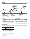
CAUTION
Support piston and gear pumps when removing
them from the pump support and pump mount
plate to prevent them from falling and causing
personal injury.
8. Remove both flange head screws (item 27) and
flange nuts (item 25)that secure pump support (item 28)
to engine mount (item 58).
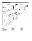
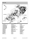
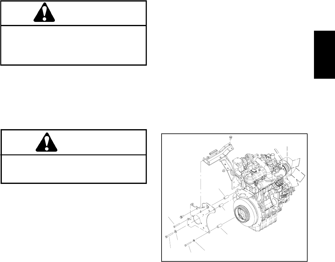
9. Remove fasteners and spacers securing the pump
mount plate to the engine (Fig. 52). Note location of cap
screws, washers and spacers for assembly purposes.
Pull pump mount plate with pumps, pump pulley, pump
support and idler assembly from the machine.
10.Remove both cap screws (item 56) and flat washers
(item 55) securing gear pump to the piston pump. Sepa-
rate gear pump from the piston pump. Locate and re-
trieve o--ring (item 54). Plug openings of gear pump to
prevent contamination.
11.If hydraulic fittings are to be removed from piston
pump, mark fitting orientation to allow correct assembly.
Remove hydraulic fittings and o--rings from the piston
pump as needed.
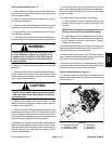
12.Remove pulley from the taper lock bushing:
A. Remove three (3) cap screws (item 36) and lock
washers (item 37) securing pulley to the taper lock
bushing.
IMPORTANT: Excessive or unequal pressure on
the cap screws can break the bushing flange.
B. Insert cap screws into threaded removal holes of
the pulley. Tighten screws progressively and evenly
until the pulley is loose on the bushing. Remove
pulley from the bushing.
13.Loosen set screw that secures taper lock bushing to
piston pump. Remove bushing from the pump shaft. Lo-
cate and retrieve key from pump shaft.
14.Remove both cap screws (item 26) and washers
(item 10) that secure piston pump to pump support (item
28). Locate and retrieve spacers (item 29).
15.Remove locknuts (item4), flatwashers (item46) and
cap screws (item 3) that secure the piston pump to the
pump mount plate. Remove pump from plate.
Piston Pump Installation (Figs. 51)
1. Position and secure piston pump to the pump mount
plate withflat washers(item 46),cap screws(item 3)and
lock nuts (item 4).
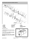
Figure 52
1. Long spacer (4 used)
2. Flat washer (3 used)
3. Cap screw (4 used)
4. Flat washer
5. Cap screw
6. Short spacer
1
2
3
4
5
6
1
3
Hydraulic
System