


Groundsmaster 3505--DPage 3 -- 14Kubota Diesel Engine
16.Separate hydrostat and pump mount plate from the
engine as follows:
A. Remove traction belt from the engine flywheel
and hydrostat pulleys (see Traction Unit Operator’s
Manual).
B. Support hydraulic pump assembly to prevent it
from falling during removal.
C. Remove five(5) capscrews, four(4) washersand
five (5)spacers securing thepump mountplate tothe
engine (Fig. 12 and 13). Note location of spacers,
washers and cap screws during removal.
D. Remove four (4) cap screws (item 12) and hard-
ened washers (item 11) securing the right engine
mounting bracket to the engine.
E. Remove hydrostat, pump mount plate and
mounting brackets from engine.
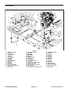
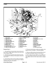
17.As necessary, remove engine mounts (item 3), front
engine mounting bracket (item 13), throttle support
bracket (item 42) and left engine mounting bracket (item
14).
Installation (Fig. 7)
1. If removed, install engine mounts (item 3), front en-
gine mountingbracket (item13), throttle supportbracket
(item 42) and left engine mounting bracket (item 14).
Also, make sure that all switches and sensors are
installed on engine.
2. Install hydrostat, pump mount plate and mounting
brackets to the engine as follows:
A. Positionhydrostat, pumpmount plate andmount-
ing brackets to engine.
B. Secure right engine mounting bracket (with hy-
drostat attached) to the engine with four (4) hard-
ened washers and cap screws.
NOTE: To prevent the torsion spring from binding,
do not install flat washer on cap screw near the
spring.
C. Using locations noted during engine removal, se-
cure pump mount plate to the engine with five (5)
spacers, four (4) washers and five (5) cap screws
(Fig. 12 and 13).
D. Install traction belt to the engine flywheel and hy-
drostat pulleys (see Traction Unit Operator’s Manu-
al).
3. Connect hoist or lift to the front and rear engine lift
tabs (Fig. 9 and 10).
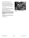
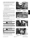
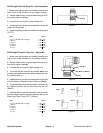
Figure 12
1. Cap screw (10 mm)
2. Short spacer
3. Torsion spring
4. Pump mount plate
5. Cap screw (8 mm)
6. Long spacer (4 used)
1
4
3
5
6
6
2
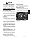
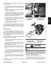
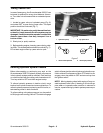
Figure 13
1. Long spacer (4 used)
2. Flat washer (3 used)
3. 8 mm cap screw (4 used)
4. Hardened washer
5. 10 mm cap screw
6. Short spacer
1
2
3
4
5
6
1
3
CAUTION
One person should operate lift or hoist while a
second person guides the engine into the ma-
chine.
IMPORTANT: Make sure not to damage the engine,
fuel or hydraulic lines, electrical harness or other
parts while installing the engine.
4. Carefully lower engine into the machine.
5. Securethree (3) enginemounts tothe engine mount-
ing brackets with cap screws, washers and flange nuts.
Kubota
Diesel Engine