


Groundsmaster 3505--D Hydraulic SystemPage 4 -- 101
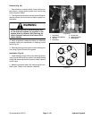
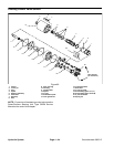
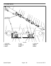
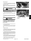
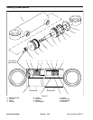
Disassembly (Fig. 66)
1. Removeoil fromlift cylinderinto a drainpan byslowly
pumping the cylinder shaft. Plug both ports and clean
the outside of the cylinder.
IMPORTANT: Prevent damage when clamping the
hydraulic cylinder into a vise; clamp on the clevis
ONLY.
2. Mount lift cylinder in a vise. Remove internal collar
with a spanner wrench.
3. Remove plugs from ports. Extract shaft, head and
piston by carefully twisting and pulling on the shaft.
IMPORTANT: Do not clamp vise jaws against the
shaft surface. Clamp on the clevis ONLY.
4. Mountshaft securely ina vise byclamping onthe cle-
vis of the shaft. Remove lock nut and piston from the
shaft. Slide head off the shaft.
5. Remove Uni--ring and o--ring from the piston. Re-
move o--ring, back--up ring, rod seal and dust seal from
the head.
Assembly (Fig. 66)
1. Make sure all parts are clean before reassembly.
2. Coat new o--rings, Uni--ring, rod seal, back--up ring
and dust seal with clean hydraulic oil.
A. Install Uni--ring and o--ring to the piston.
B. Install dust seal, o--ring, back--up ring and dust
seal to the head.
IMPORTANT: Do not clamp vise jaws against the
shaft surface. Clamp on the clevis ONLY.
3. Mountshaft securely ina vise byclamping onthe cle-
vis of the shaft.
A. Coat shaft with clean hydraulic oil.
B. Slide head onto the shaft. Install rod seal onto
shaft and into head.
C. Install piston and lock nut onto the shaft. Torque
lock nut from 24 to 30 ft--lb (33 to 41 N--m).
D. Remove shaft from the vise.
IMPORTANT: Prevent damage when clamping the
hydraulic cylinder into a vise; clamp on the clevis
ONLY.
4. Mount barrel in a vise.
5. Coat all internal parts with a light coat of clean hy-
draulic oil. Slide piston, shaft and head assembly into
the barrel being careful not to damage the seals.
6. Secure head in the barrel w ith internal collar using a
spanner wrench. Tighten collar until snug and the outer
end of the c ollar is flush with end of the barrel.
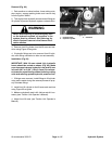
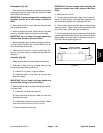
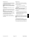
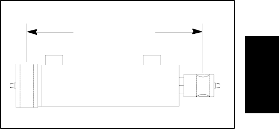
7. Ifclevis was removed fromcylinder shaft, fully retract
cylinder shaft and thread jam nut and clevis onto shaft.
Adjust center to center length to dimension shown in
Figure 67 before tightening jam nut.
Figure 67
10.125” to 10.500”
(25.72 to 26.67 cm)
Hydraulic
System