


Groundsmaster 3505--D Page 3 -- 13 Kubota Diesel Engine
7. Remove coolant expansion tank and bracket from
the upper fan shroud. Remove upper fan shroud from
the radiator (see Radiator Removal in this section).
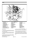
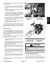
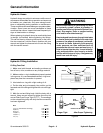
8. Disconnect electrical wires from engine:
A. Negative battery cable, wire harness ground and
fuel stop solenoid ( Fig. 8).
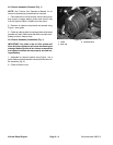
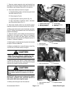
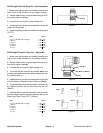
B. Glow plug bus (Fig. 9).
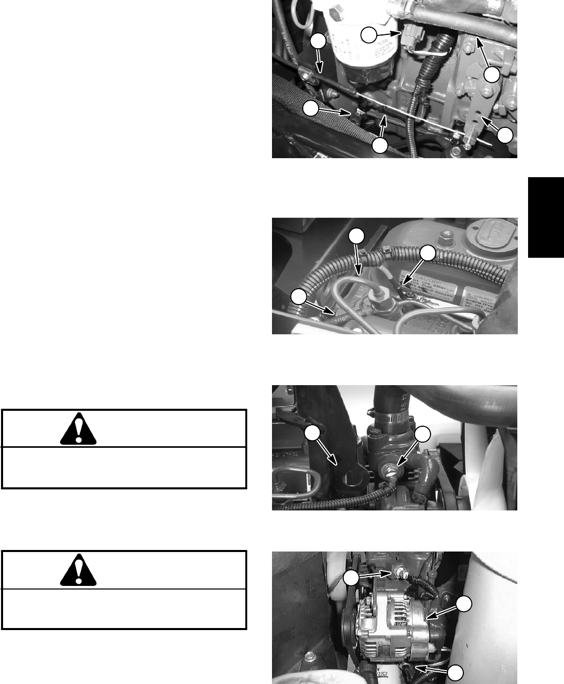
C. High temperature warning switch (Fig. 10).
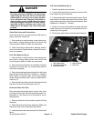
D. High temperature s hutdown switch, alternator
and oil pressure switch (Fig. 11).
9. Disconnect throttle cable from the throttle s upport
bracket and swivel on the speed control lever (Fig. 8).
10.Disconnect fuel hoses from the fuel/water separator
(Fig. 8). Position disconnected hose from fuel pump to
prevent fuel leakage.
11.Remove traction control cable from the neutral arm
assembly on the piston pump. Remove all hydraulic
hoses from the piston and gear pumps (see Piston
Pump Removal in the Service and Repairs section of
Chapter 4-- Hydraulic System).
12.Note location of cable ties securing the wire harness
to engine. Remove cable ties.
13.Attach a suitable lift or hoist to lift tabs on front (Fig.
10) and rear (on air filter mount) of engine.
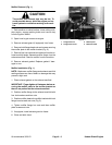
CAUTION
Make sure lift or hoist can support the total
weight of the engine before removing the cap
screws from the engine and engine brackets.
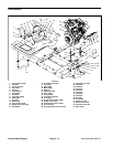
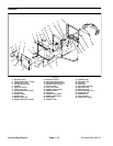
14.Remove flange nuts (item 4), flange head screws
(item 6) and lock washer (item 7) securing three engine
mounts to the engine mounting brackets.
CAUTION
One person should operate lift or hoist while a
second person guides the engine out of the ma-
chine.
IMPORTANT: Make sure not to damage the engine,
fuel hoses, hydraulic lines, electrical harness or
other parts while removing the engine.
15.Slowly remove engine from the machine.
Figure 8
1. Negative battery cable
2. Wire harness ground
3. Fuel stop solenoid
4. Throttle cable
5. Speed control lever
6. Fuel hose
6
5
2
1
4
3
Figure 9
1. Glow plug wire
2. Rear injector nozzle
3. Fuel hose
1
2
3
Figure 10
1. Temp. warning switch 2. Front lift tab
1
2
Figure 11
1. Temp. shutdown switch
2. Alternator
3. Oil pressure switch
2
3
1
Kubota
Diesel Engine