Groundsmaster 3505--D Page 6 -- 7 Chassis
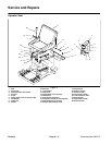
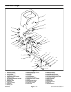
Removal (Fig. 4)
1. Park machine on a level surface, lower cutting units,
stop engine, engage parking brake and remove key
from the ignition switch.
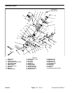
2. Remove two ( 2) flange head screws (item 13) and
two (2) cap screws (item 25) with flat washers (item 7)
that secure the seat support straps to the frame. Note
location of spacers under front of seat support straps.
3. Disconnect wire harness electrical connector from
the seat switch. Separate seat from the frame.
4. Remove seatparts as necessary tomake repairs us-
ing Figure 4 as a guide.
Installation (Fig. 4)
1. Install any new seat parts using Figure 4 as a guide.
2. Position seat, spacers and support straps to the fuel
tank and frame.
3. Connect wire harness electrical connector to the
seat switch.
4. Secure seat support straps to the machine with two
(2) flange head screws ( item 13) and two (2) cap screws
(item 25) with flat washers (item 7).
Chassis


