


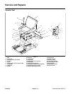
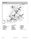
Groundsmaster 3505--D Page 6 -- 9 Chassis
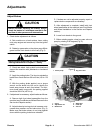
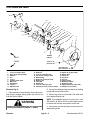
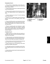
IMPORTANT: Do not hit wheel hub or puller with a
hammer during removal or installation. Hammering
may cause damage to the hydraulic wheel motor.
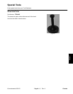
5. Usewheel hubpuller to remove wheelhub andbrake
drum from the hydraulic motor shaft (see Special Tools
in this chapter). Remove woodruff key from the shaft.
6. Remove cotter pin that retains adjustment rod to
brake lever. Separate adjustment rod from brake lever.
NOTE: The brake lever, backing plate, retainer clip, re-
turn springs, brake shoes and cam shaft can be re-
moved as a complete brake assembly.
7. If it is desired to remove the brake assembly from the
brake bracket,remove fourcap screwsand locknuts se-
curing the assembly to the bracket.
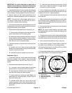
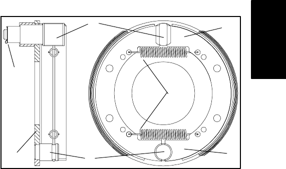
8. Disassemble brake assembly as follows (Fig. 6):
A. Removereturn springs fromthe brake shoes.Re-
move brake shoes from the backing plate.
B. Matchmark brake cam and brake lever to assure
proper alignment during assembly. Remove retain-
ing clip from the brake cam. Pull brake lever from the
cam. Remove cam from backing plate.
9. The brake bracket and wheel shield can be removed
as follows:
A. Remove lock nuts, spacers and socket head
screws securing the brake bracket, wheel shield and
hydraulic motor to the frame.
B. Separate bracket and shield from the frame.
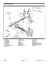
Installation (Fig. 5)
1. If removed, insert four socket head screws through
the frame, hydraulic motor, spacers, wheel shield and
brake bracket. Secure with lock nuts, but do not fully
tighten.
2. Assemble brake assembly as follows (Fig. 6):
A. If removed, secure backing plate to the brake
bracket with four cap screws and lock washers.
B. Apply antiseize lubricant to cam shaft splines. In-
sert cam shaft through the backing plate.
C. Attach brake lever to the cam shaft. Make sure
matchmarks are aligned properly. Secure lever to
shaft with retainer clip.
D. Lubricate brake shoe pivot points with a light
coating of grease. Position both brake shoes on the
backing plate so that the concave heels attach to the
anchor pin.
E. Insert both return springs into the holes of both
brake shoes. Make sure shoes fit snuggly against
the anchor pin and cam shaft.
3. If the complete brake assembly was removed, se-
cure brake assembly to the brake bracket with four cap
screws and lock nuts. Tighten fasteners.
4. Attach adjustment rod to the brake lever and secure
with cotter pin.
5. Makesure that wheelhub and hydraulic motorshafts
are thoroughly clean. Install key to the slot on the hy-
draulic motor s haft. Slide wheel hub and brake drum as-
sembly onto the shaft.
6. Secure wheel hub and brake drum to the hydraulic
motor shaft with lock nut.
NOTE: For proper brake operation, the brake shoes
and backing plate must be concentrically aligned with
the brake drum.
7. To align brake shoes and drum, apply parking brake.
Then tighten four socket head screws and lock nuts that
secure the brake bracket and wheel motor to the frame.
8. Secure wheel to machine with four (4) lug nuts.
9. Lower wheel to ground. Torque wheel lug nuts from
45to65ft--lb(61to88N--m)inacrossingpattern.
10.Torque lock nut (item 6) from 250 to 350 ft--lb (339 to
474 N--m). Release parking brake.
11.Check brake adjustment and andadjust if necessary
(see Adjust Brakes in the Adjustments section).
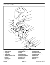
1. Return spring
2. Brake shoe (toe end)
3. Brake shoe (heel end)
4. Backing plate
5. Retaining clip
6. Cam shaft
7. Anchor pin
Figure 6
1
4
6
7
3
2
5
Chassis