Rev. A
Groundsmaster 3505--D Page 7 -- 7 Cutting Units
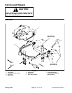
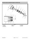
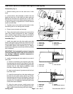
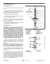
Removal (Fig. 4)
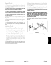
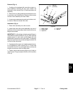
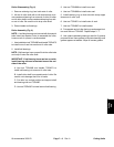
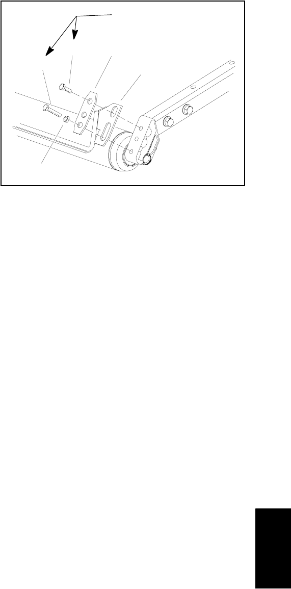
1. If cutting unit is equipped with rear roller scraper, re-
move fasteners securing left and right scraper rod
brackets to roller mounts (Fig. 5). Remove scraper rod
assembly.
2. Remove four (4) flange head screws that secure roll-
er mounts to rear of deck frame. Remove roller mounts
and rear roller assembly from deck frame.
3. Loosencap screwssecuring eachend ofrollerto roll-
er mounts. Remove mounts from roller.
Installation (Fig. 4)
1. Place roller assembly into roller mounts.
2. Install roller and roller mount assembly into rear of
deck frame.Secure assemblyto deckframe with four(4)
flange head screws.
IMPORTANT: If roller design includes grease fittings in
roller fasteners (items 9 and 10 in Fig. 4), make sure the
grease groove in each roller mount aligns with the
grease hole in each end of the roller shaft. To help align
the groove and hole, there is also an alignment mark on
one end of the roller shaft.
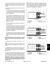
3. If equippedwith scraper rod, install andadjust scrap-
er rod assembly to roller mounts (Fig. 5). Torque cap
screws 30 ft --lb (41 N--m) and tighten jam nut to secure
scraper rod and rear roller to cutting deck.
4. Tighten cap screws securing each end of roller to
roller mounts. Torque screws from 29 to 35 ft --lb (39 to
47 N--m).
1. Roller scraper
2. Scraper plate
3. Cap screw
4. Cap screw
5. Jam nut
Figure 5
3
5
4
2
1
30 ft--lb
(41 N--m)
Cutting
Units


