


Rev. A
Groundsmaster 3505--D Page 7 -- 11 Cutting Units
3. From the roller tube end with only the inner seal
installed, carefully install the roller shaft into the roller
tube. Make sure that seals are not damaged as shaft is
installed.
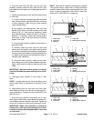
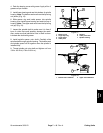
4. Install new bearing and outer seals into second end
of roller tube:
A. Position a second new bearing to roller shaft and
tube. Position washer(see Special Tools) on bearing
to allow pressing on both inner and outer bearing
races simultaneously.
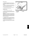
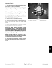
B. Use washer and bearing/outer seal tool (see
Special Tools) with a soft face hammer to fully seat
bearing (Fig. 11). After bearing installation, make
sure that shaft freely rotates and that no binding is
detected. If necessary, lightly tap bearing and/or
shaft ends to align shaft and bearings. Remove
washer from roller.
C. Apply a small amount of grease around the lip of
both outer seals.
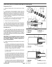
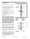
D. Carefully install first outer seal into roller tube
making sure that seal lip (and garter spring) faces
end of tube. Use bearing/outer seal tool (see Special
Tools) and soft face hammer to lightly seat seal (Fig.
12). Make sure that shaft and bearings still freely ro-
tate after seal installation.
E. Using the same process, install second outer
seal makingsure tonot crush the installedouter seal.
Again, make sure that shaft and bearings still freely
rotate.
IMPORTANT: Make sure that all grease is removed
from shaft threads to prevent bearing lock nut loos-
ening.
5. Thoroughly clean threads on both ends of roller
shaft.
NOTE: If original bearing lock nut(s) are being used,
apply Loctite #242 (or equivalent) to threads of lock
nut(s).
6. Install bearing lock nut onto each end of the roller
shaft. Make sure that outer seals are not damaged dur-
ing nut installation. Torque lock nuts from 50 to 60 ft--lb
(68to81N--m).
7. If set screw was removed from either end of roller
shaft, apply Loctite #242 (or equivalent) to threads of re-
moved set screw and install into roller shaft. Tighten set
screw until it bottoms in shaft and is recessed in shaft.
IMPORTANT: When roller assembly is installed to
cutting deck, make sure that grease groove in each
roller mount aligns with the grease hole in each end
of roller shaft.
NOTE: After roller is installed to cutting deck, lubricate
roller grease fittings, rotate roller to properly distribute
grease in bearings and clean excess grease from roller
ends. A properly assembled roller should rotate w ith
less than 5 in--lbs (0.68 N--m) resistance.
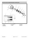
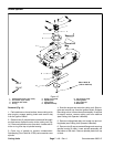
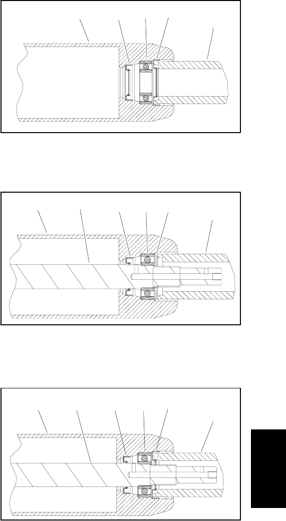
1. Roller tube
2. Inner seal
3. Bearing
4. Outer seal
5. Bearing/outer seal tool
Figure 10
3
4
2
1
5
1. Roller tube
2. Roller shaft
3. Inner seal
4. Bearing
5. Washer
6. Bearing/outer seal tool
Figure 11
34
2
1
5
6
1. Roller tube
2. Roller shaft
3. Inner seal
4. Bearing
5. Outer seal
6. Bearing/outer seal tool
Figure 12
3
4
2
1
5
6
Cutting
Units