


Groundsmaster 3505--DPage 5 -- 16Electrical System
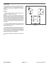
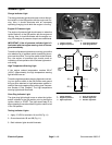
High Temperature Warning Switch
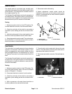
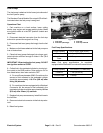
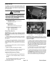
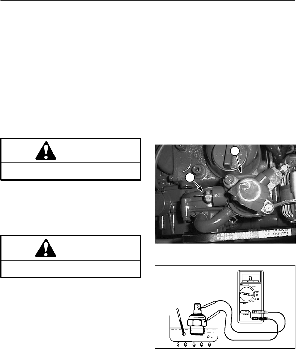
The high temperature warning switch is located on the
water pump housing on the rearof the engine block (Fig.
20). The high temperature warning switch has a gray
wire connected to it.
The Standard Control Module monitors the operation of
the high temperature warning switch. If the ignition
switch is in the ON position and the high temperature
warning s witch has closed due to excessive coolant
temperature, the Module Over Temperature Warning in-
put LED should be illuminated. The high temperature in-
dicator light on the c ontrol panel should also illuminate.
If thecutting decks are engagedwhen the hightempera-
ture warning switch closes, the decks should shut off.
Testing
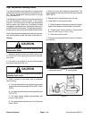
CAUTION
Make sure engine is cool before removing the
temperature switch.
1. Makesure ignition switchis in theOFF position.Low-
er coolant level in the engine and remove the tempera-
ture switch.
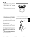
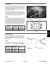
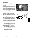
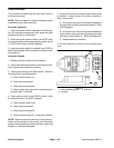
2. Put switch in a container of oil with a thermometer
and slowly heat the oil (Fig. 21).
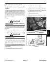
CAUTION
Handle the hot oil w ith extreme care to prevent
personal injury or fire.
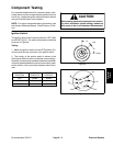
3. Check continuity of the switch with a multimeter
(ohms setting).
A. The high temperature warning switch is normally
open and shouldclose between 216 to226
o
F (102 to
108
o
C).
B. The meter shouldindicate more than600 ohmsat
70
o
F(21
o
C).
C. The meter should indicate approximately 460
ohms at 100
o
F(38
o
C).
D. The meter should indicate from 54 to 78 ohms at
200
o
F(93
o
C).
4. Allow oil to cool while observing temperature. The
high temperature warning switch should open at about
208
o
F(98
o
C).
5. Replace switch if specifications are not met.
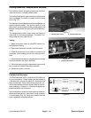
6. Install switch to the engine housing.
A. Clean threads of housing and switch thoroughly.
Apply thread sealant to the threads of the switch.
B. Thread switch into the housing. Torque switch
from 16 to 20 ft--lb (21.7 to 27.1 N--m).
C. Reconnect wire to switch.
7. Fill engine cooling system (see Traction Unit Opera-
tor’s Manual).
1. Water pump housing 2. Warning switch
Figure 20
1
2
Figure 21