


Groundsmaster 3505--D Page 5 -- 15 Electrical System
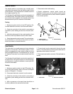
Parking Brake and Transport/Mow Switches
The switches used for the parking brake and transport/
mow are the same, normally closed switch.
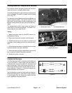
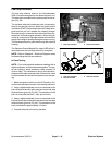
The parking brake switch opens whenthe parking brake
lever is engaged. The switch is located under the dash
cover (Fig. 17).
The Standard Control Module monitors the operation of
the parking brake switch. If the ignition switch is in the
ON position and the parking brake is disengaged, the
Module Parking Brake Off input LED should be illumi-
nated.
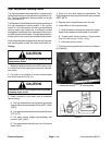
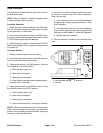
The transport/mow switch opens when the transport/
mow slide is in the transport position. The switch is lo-
cated under the floor plate (Fig 18).
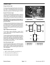
Testing
1. Make sure ignition switch is in the OFF position. Lo-
cate switch for testing.
2. Disconnect electrical connector from the switch.
3. Check the continuity of the switch by connecting a
multimeter (ohms setting) across the connector termi-
nals.
4. Whenthe switch plunger isextended thereshould be
continuity between the switch terminals.
5. When the switch plunger is depressed, there should
be no continuity between the switch terminals.
6. Reconnect switch connector.
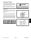
1. Parking brake switch 2. Parking brake lever
Figure 17
1
2
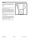
1. Transport/Mow switch
Figure 18
1
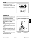
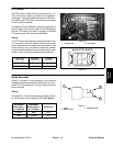
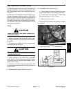
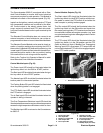
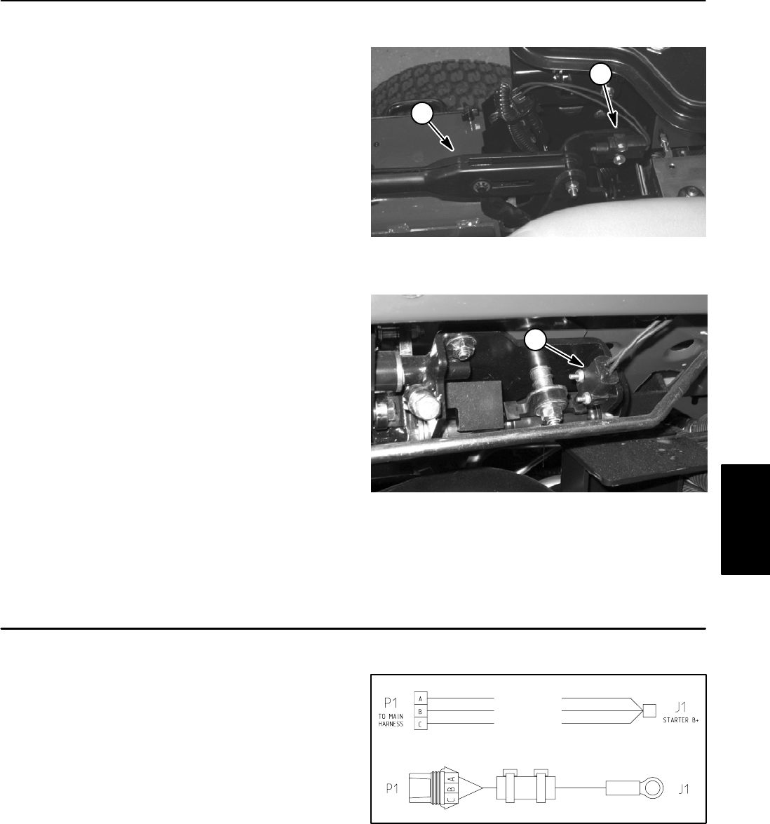
Fusible Link Harness
The Groundsmaster 3505--D uses three (3) fusible links
for circuit protection. These fusible links are located in
a harness that connects the starter B+ terminal to the
main wire harness. If any of these links should fail, cur-
rent to the protected circuit will cease. Refer to wire har-
ness drawings in Chapter 8 -- Electrical Diagrams for
additional fusible link information.
Use a multimeter to make sure that continuity exists be-
tween each terminal pin in connector P1 and connector
J1 at the starter (Fig. 19). If any of the fusible links are
open, replace the complete harness.
Figure 19
FUSIBLE LINK
FUSIBLE LINK
FUSIBLE LINK
Electrical
System