


Groundsmaster 3505--D Hydraulic SystemPage 4 -- 65
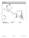
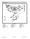
IMPORTANT: Note position of the open and closed
side of the wear plates before removing. Also, iden-
tify wear plates (front and rear) for proper re-
assembly. Do not scribe wear plates.
8. Carefully remove rear wear plate, idler gear, drive
gear and front wear plate from the front plate.
9. Remove and discard back--up gaskets and pressure
seals from wear plates.
IMPORTANT: Make sure not to damage the front
plate counter bore when removing the components
from the front plate.
10.Turn front plate over, with seal side up and carefully
remove the seal, retaining ring, washer and shaft seal.
Discard seals.
11.If necessary, remove anti--cavitation and relief
valves from back plate.
Inspection
1. Remove any nicks and burrs from all parts with
emery cloth.
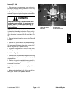
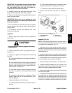
CAUTION
Use eye protection such as goggles when using
compressed air.
2. Clean all parts with solvent. Dry all parts with com-
pressed air.
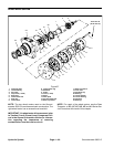
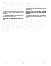
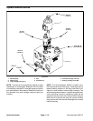
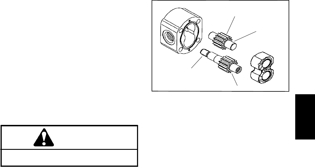
3. Inspect drive gears and idler gears for the following
(Fig. 42):
A. Drivegear shaftspline shouldbe freeof twistedor
broken teeth.
B. Gear shafts should be free of rough surfaces and
excessive wear at bushing points and sealing areas.
Scoring, rough surfaces or wear on gear shafts indi-
cates need for replacement.
C. Gear teeth should be free of excessive scoring
and wear. Any broken or nicked gear teeth must be
replaced.
D. Inspect gear face edge for sharpness. Sharp
edges of gears will mill into wear plates and, thus,
must be replaced.
4. Inspect wear plates for the following:
A. Bearing areasshould not have excessive wearor
scoring.
B. Face of wear plates that are in contact with gears
should be free of wear, roughness or scoring.
C. Thickness of wear plates should be equal.
5. Inspect front plate and back plate for damage or
wear.
1. Gear shaft spline
2. Gear shaft
3. Gear teeth
4. Gear face edge
Figure 42
3
4
1
2
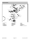
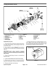
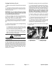
Assembly (Fig. 40)
NOTE: When assembling the motor, check the marker
line oneach partto makesure the componentsare prop-
erly aligned during assembly (Fig. 41).
1. Lubricate new o--rings, pressure seals, back--up
gaskets and wearplate grooves with a thin coatof petro-
leum jelly. Lubricate all other internal parts freely with
clean hydraulic oil.
2. Install new shaft seal in front plate. Seal should be
pressed intoplace until itreaches the bottomof thebore.
3. Install washer and then retaining ring into the groove
of the front plate. Press seal into front plate.
4. Place front plate, seal side down, on a flat surface.
5. Install the backup gaskets into the grooves in the
wear plates. Follow by carefully placing the pressure
seals to the backup gaskets and wear plate.
6. Apply alight coating of petroleumjelly tothe exposed
side of the front plate.
7. Lubricatethe drivegear shaft with cleanhydraulic oil.
Insert the drive end of the drive shaft through the front
wear plate with the pressure seal side down and the
open side of the pressure seal pointing to the inlet side
of the motor. Carefully install drive shaft into front plate.
Hydraulic
System