


Groundsmaster 3505--D Hydraulic SystemPage 4 -- 15
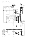
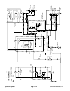
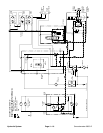
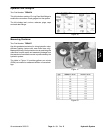
Lift Circuit (Lower)
Circuit operation for lowering the cutting units is similar
to raising them. However, pressure is relieved from the
lift cylinders and this action allows the cutting units to
lower.
During conditions of not lifting or lowering cutting units,
flow from gear pump (P2) is by--passed through the
steering control valve, lift control valve and hydraulic
manifold directly to the hydrostat (charge). Flow then re-
turns to gear pump (P1) inlet.
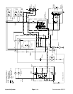
When the cutting units are to be lowered, the lift control
valve is positioned by moving the lift control lever to
LOWER. Pressure from gear pump (P2) is used to shift
the pilot valvein the control valve.This shifted pilot valve
allows hydraulic pressure to relieve from the cap end of
the lift cylinders. Flow from the cap end of the lift cylin-
ders causes the cutting units to lower. At the same time,
the fluid relieved from the cap end of the lift cylinders
goes into the rod end of the cylinders and back through
the hydraulic manifold block to the hydrostat (charge).
When the lift control lever is released, spring action re-
turns the valve to its original position and by--passes
flow back to the hydrostat (charge). The pilot valve re-
mains shifted to allow the lift cylinders to float until the
lift control valve is moved to the raise position.
The logic cartridge valve (LC1) in the manifold block
maintains 250 PSI (17.2 bar) back pressure on the lift
cylinders. This counterbalance pressure transfers cut-
ting unit weight to the machine to improve traction.
Hydraulic
System