


Groundsmaster 3505--DHydraulic System Page 4 -- 78
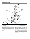
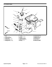
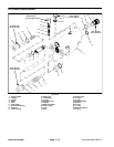
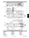
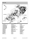
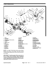
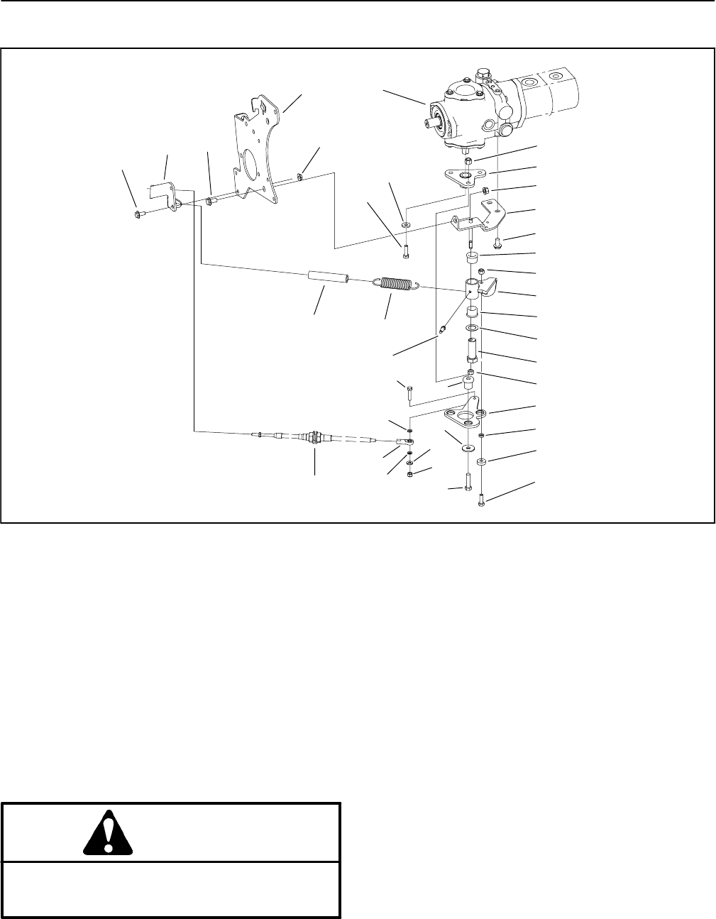
Neutral Arm Assembly
1. Pump assembly
2. Hose
3. Extension spring
4. Pump mount plate
5. Neutral bracket
6. Flange nut
7. Flange head screw (3 used)
8. Neutral arm
9. Flange bushing
10. Thrust washer
11. 90
o
grease fitting
12. Lock nut (2 used)
13. Spacer
14. Traction stud
15. Traction control cable
16. Flat washer
17. Ball joint
18. Lock nut (3 used)
19. Cap screw
20. Flat washer
21. Hub assembly
22. Flange nut (2 used)
23. Flange head screw (2 used)
24. Cable support bracket
25. Ball bearing
26. Flat washer
27. Lock nut
28. Socket head screw (3 used)
29. Pump lever
30. Cap screw
31. Flat washer (3 used)
32. Cap screw
33. Mount (3 used)
Figure 50
21
6
5
7
9
12
8
10
14
12
13
25
27
20
19
22
7
24
23
17
16
32
16
11
2
9
1
3
18
4
26
29
30
31
33
28
15
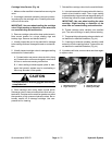
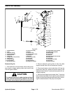
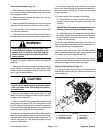
Removal (Fig. 50)
1. Park machine on a level surface, lower cutting units,
stop engine, engage parking brake and remove key
from the ignition switch.
CAUTION
The extension spring is under tension and may
cause personal injury during removal. Use cau-
tion when removing spring from the pump lever.
2. Remove extension spring (item 3) from the cable
support bracket (item 24) and neutral arm (item 8).
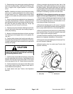
3. Disconnect traction control c able (item 15) from the
pump lever (item 29). Locate and retrieve three (3) flat
washers (items 16 and 17) and note their position for as-
sembly purposes.
4. Remove both flange head screws (item 7) securing
the neutral bracket (item 5) to the piston pump. Remove
flange nut(item 6) and flangehead screw (item7) secur-
ing the neutral bracket to the pump mount plate.