


Rev. A
Groundsmaster 3505--DPage 7 -- 12Cutting Units
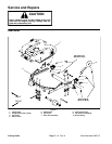
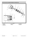
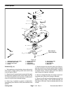
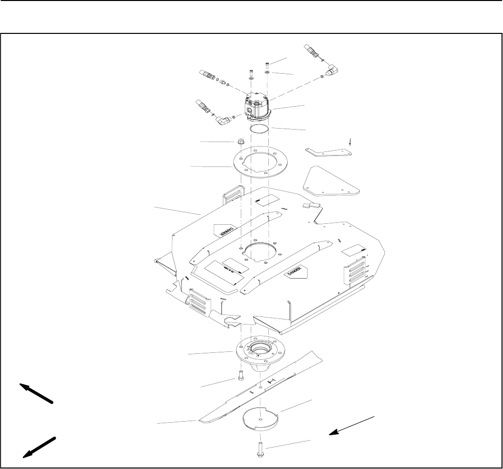
Blade Spindle
1. Socket head screw (2 per motor)
2. Flat washer (2 per motor)
3. Hydraulic deck motor
4. O--ring
5. Flange nut (6 used)
6. Spindle plate
7. Cutting deck
8. Spindle assembly
9. Cap screw (6 used)
10. Cutting blade
11. Anti--scalp cup
12. Blade bolt
Figure 13
FRONT
RIGHT
6
11
8
9
7
12
10
3
5
4
2
1
88 to 108 ft--lb
(119 to 146 N--m)
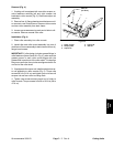
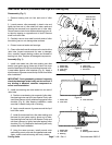
Removal (Fig. 13)
1. Park machine on a level surface, lower cutting units,
stop engine, engage parking brake and remove key
from the ignition switch.
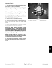
2. Remove two (2) socket head screws and flat wash-
ers that secure hydraulic motor to the cutting unit ( Fig.
14). Remove hydraulic motor from deck. Locate and re-
trieve o--ring from top of spindle housing.
3. Cover top of spindle to prevent contamination.
Spindle plug (ToroPart # 94--2703) can be used to cover
spindle.
4. Start the engine and raise the cutting unit. Stop en-
gine and remove key from the ignition switch. Support
the cuttingunit so itcannot lower accidentally.If required
for easier service, remove cutting unit from machine
(see Cutting Unit Operator’s Manual).
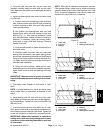
5. Remove cutting blade bolt, anti--scalp cup and cut-
ting blade (see Cutting Unit Operator’s Manual).
6. Remove six ( 6) cap screws and flange nuts securing
spindle housing to deck. Lower spindle assembly out
the bottom of the deck. Remove spindle plate from top
of deck.