


Groundsmaster 3505--D Hydraulic SystemPage 4 -- 39
Procedure for Logic (Counterbalance) Valve
(LC1)
Pressure
Test:
NOTE: If the counterbalance system is functioning, the
machine should normally settle slightly when the engine
is started.
1. Make sure hydraulic oil is at normal operating tem-
perature.
2. Park machine on a levelsurface with the cuttingunits
lowered and off. Make sure engine is off and the parking
brake is engaged.
3. Read Precautions for Hydraulic Testing.
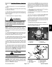
WARNING
Before disconnecting or performing any work
on the hydraulic system, all pressure in the
system must be relieved. See Relieving Hy-
draulic System Pressure in the General Infor -
mation section.
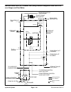
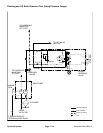
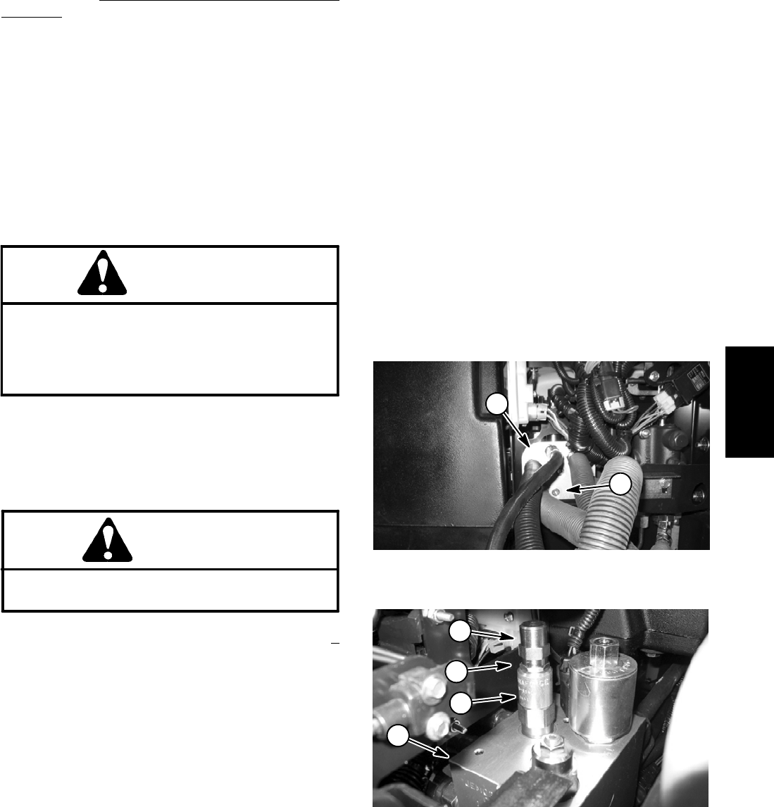
4. Remove plug from hydraulic manifold port (G2) (Fig.
25).
5. Install hydraulic pressure gauge with hydraulic hose
attached to port (G2).
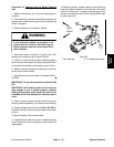
CAUTION
Keep awayfrom decks duringtest to prevent per-
sonal injury from the cutting blades.
6. Start engine and move throttle to full speed (3050 +
50 RPM). Do not engage or raise the cutting units.
7. The standard counterbalance pressure should be
250 PSI with a range of 180 to 300 psi.
8. Ifnecessary, adjustmentof theLogic valve (LC1)can
be performed as follows:
NOTE: Do not remove the Logic valve from the hy-
draulic manifold for adjustment.
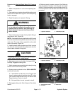
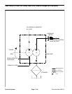
A. Remove hex cap from logic valve (Fig. 26).
B. Loosen lock nut.
C. To increase pressure setting, turn the adjust-
ment shafton the valvein a clockwise direction.A 1/8
turn on the shaft will make a measurable change in
counterbalance pressure.
D. To decrease pressure setting, turn the adjust-
ment shaft on the valve in a counterclockwise direc-
tion. A 1/8 turn on the shaft will make a measurable
change in counterbalance pressure.
E. Tighten locknut. Checkc ounterbalance pressure
(steps 6 and 7) and readjust as needed.
F. Replace hex cap to Logic valve (LC1).
9. Shut off engine.
10.Relieve hydraulic system pressure (See Relieving
Hydraulic System Pressure in the General Information
section). Disconnecttest gauge withhose frommanifold
block. Install plug into hydraulic manifold port (G2) and
torque plug 120 in--lb (13.6 N--m).
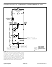
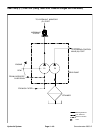
1. Hydraulic manifold 2. Manifold port (G2)
Figure 25
2
1
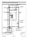
1. Manifold assembly
2. Logic valve (LC1)
3. Hex cap
4. Lock nut
Figure 26
2
1
3
4
Hydraulic
System