


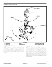
Groundsmaster 3505--D Hydraulic SystemPage 4 -- 63
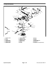
Removal (Fig. 38)
1. Park machine on a level surface, lower cutting units,
stop engine, engage parking brake and remove key
from the ignition switch.
2. Thoroughly clean hydraulichose ends and fittingson
deck motor to prevent hydraulic system contamination.
WARNING
Before disconnecting or performing any work
on the hydraulic system, all pressure in the
system must be relieved. See Relieving Hy-
draulic System Pressure in the General Infor -
mation section.
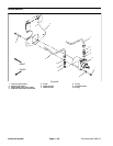
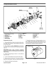
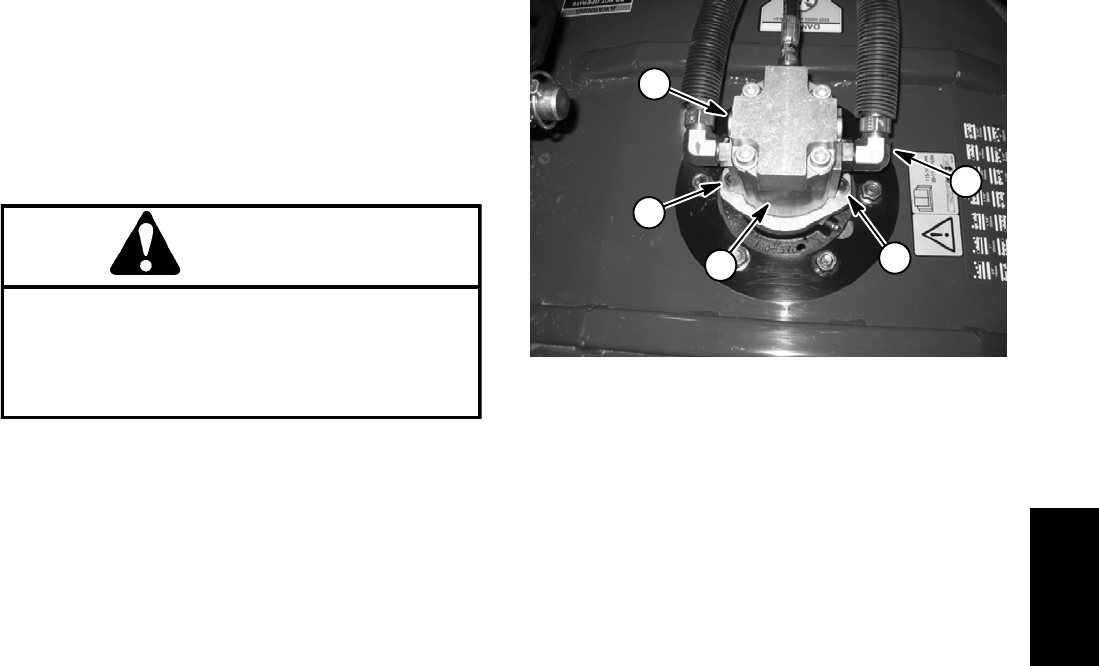
NOTE: Note position of hydraulic hoses when remov-
ing hoses from the cutting deck motors. Proper position-
ing is critical when reconnecting hydraulic hoses. The
inlet to the motor is opposite from the relief valve (Fig.
39).
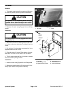
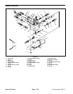
3. Remove hydraulic hoses from motor using Figure 38
as a guide.
4. Remove two (2) socket head screws and flat wash-
ers that secure hydraulic motor to the cutting unit ( Fig.
39). Remove hydraulic motor from deck. Locate and re-
trieve o--ring from top of spindle housing.
5. If hydraulic fittings are to be removed from motor,
mark fitting orientation to allow correct assembly.
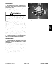
Installation (Fig. 38)
1. If fittings were removed, install fittings to motor using
marks made during the removal process to properly
orientate fittings.
2. Position o--ring to top of spindle housing. Install hy-
draulic motor to the cutting unit with two (2) socket head
screws and flat washers.
3. Install hydraulic hoses to motor using Figure 38 as a
guide.
4. Make surehydraulic tank is full. Add correct oilif nec-
essary (see Traction Unit Operator’s Manual).
1. Cutting deck motor
2. Inlet hose
3. Relief valve
4. Socket head screw
Figure 39
4
2
1
4
3
Hydraulic
System