


Groundsmaster 3505--D Page 5 -- 21 Electrical System
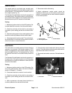
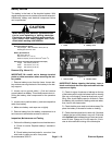
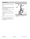
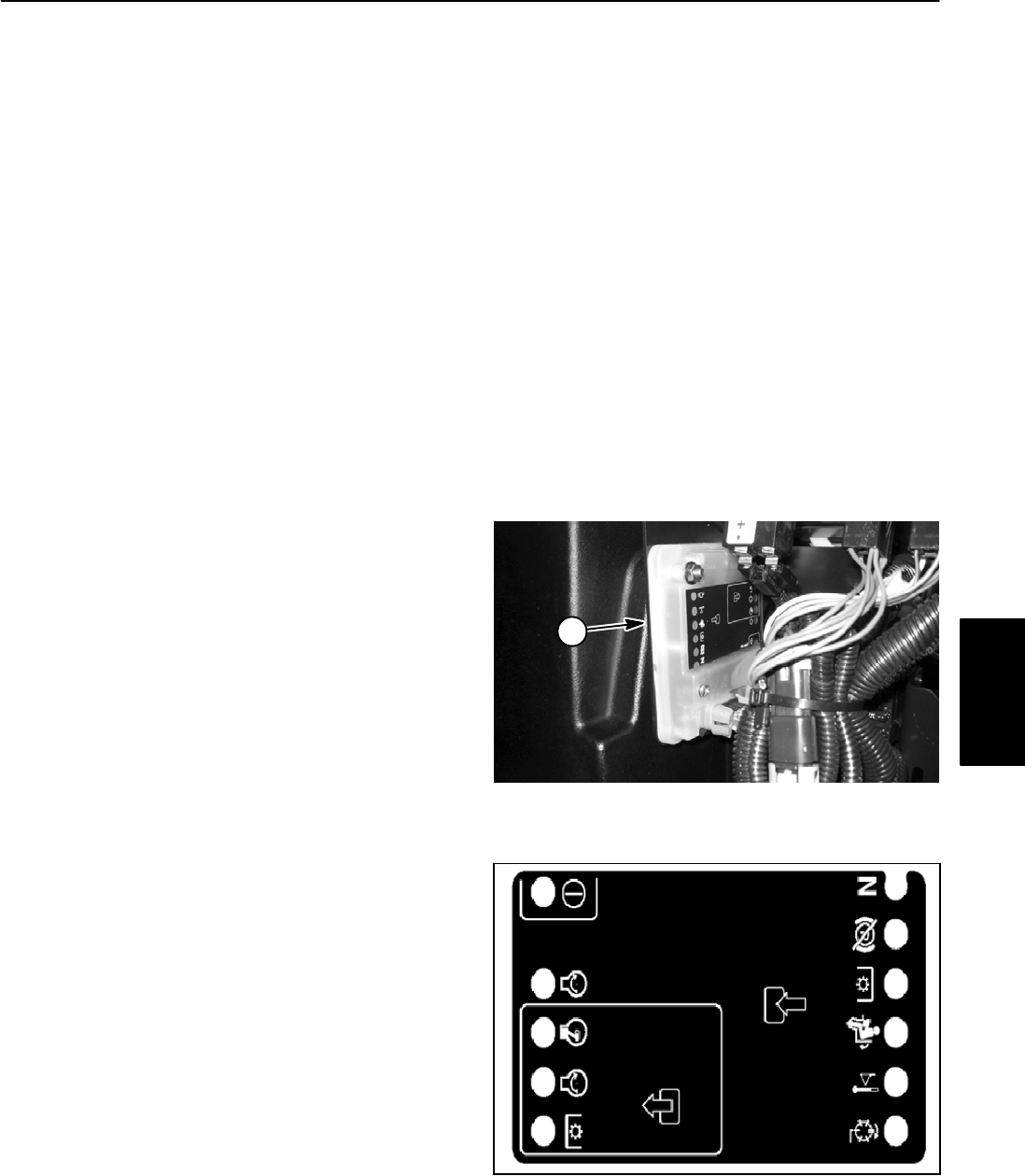
Standard Control Module
The Groundsmaster 3505--D is equipped with a Stan-
dard Control Module to monitor and control electrical
components required for safe operation. This Module is
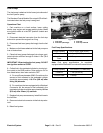
attached to the back of the instrument panel (Fig. 28).
Inputs from the ignition, neutral,parking brake, PTO and
high temperature switches are monitored by the Mod-
ule. Current output to the electric starter motor, fuel
pump, engine run solenoid and PTO (deck drive sole-
noid) are controlled based on the inputs received by the
Module.
The Standard Control Module does not connect to an
external computer or hand held device, can not be re--
programmed and does notrecord intermittent fault data.
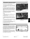
The Standard Control Module can be used to check op-
eration of machine switches by monitoring the LED of
the module.If aModule LEDdoes not illuminate(e.g. the
in seat input LED does not illuminate with the seat occu-
pied and the ignition switch in the run position), testing
of the switch and circuit wiring would be required.
Refer to the Tr action Unit Operator’s Manual for addi-
tional Standard Control Module information.
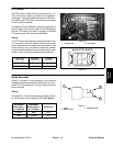
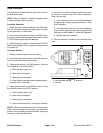
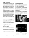
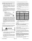
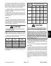
Control Module Inputs (Fig. 29)
The Power input LED should be illuminated when the
ignition key switch is in the RUN or START position.
The Start input LED should be illuminated whenthe igni-
tion key switch is in the START position.
The Neutral input LED should be illuminated when the
traction pedal is in the neutral position.
The Parking Brake Off input LED should be illuminated
when the parking brake is not engaged.
The PTO Switch input LED should be illuminated when
the PTO switch is engaged.
The In Seat input LED should be illuminated when the
operator is sitting in the seat.
The Over Temperature Shutdown input LED should be
illuminated whenexcessive enginecoolant temperature
causes the high temperature shutdown switch to close.
The Backlap input LED is not used on the Groundsmas-
ter 3505--D.
Control Module Outputs (Fig. 29)
The Start output LED should be illuminated when the
ignition key switch is in the START position with the trac-
tion pedal in neutral, the PTO switch off and either the
seat occupied or parking brake engaged.
The Run output LED should be illuminated when the
ignition key switch is in the ON position and inputs from
the neutral, parking brake,PTO, seat and overtempera-
ture switches indicate safe engine operation (e.g. seat
occupied and parking brake disengaged when traction
pedal is depressed).
The PTO output LED should be illuminated when the
ignition key switch is in the ON position and the PTO
switch is pulled out. Note: If Module Over Temperature
Warning input LED is illuminated, PTO output LED will
not be illuminated and PTO will not be engaged regard-
less of PTO switch position.
1. Standard Control Module
Figure 28
1
1. Power input LED
2. Start input LED
3. Engine run output LED
4. Start output LED
5. PTO output LED
6. Neutral input LED
7. Park brake off input LED
8. PTO switch input LED
9. In seat input LED
10. High temp input LED
11. Backlap input (not used)
Figure 29
1
2
3
4
5
6
7
8
9
10
11
Electrical
System