


Groundsmaster 3505--D Hydraulic SystemPage 4 -- 41
Procedure for Gear Pump (P1) Flow
Test:
NOTE: Overa period of time,the gears and wearplates
in the pump can wear. A worn pump will by pass oil and
make thepump lessefficient.Eventually, enoughoil loss
will occur to cause the cutting unit motors to stall under
heavy cutting conditions. C ontinued operation with a
worn, inefficient pump can generate excessive heat and
cause damage to the seals and other components in the
hydraulic system.
1. Make sure hydraulic oil is at normal operating tem-
perature.
2. Park machine on a levelsurface with the cuttingunits
lowered and off. Make sure engine is off and the parking
brake is engaged.
3. Read Precautions for Hydraulic Testing.
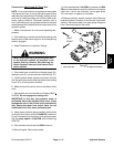
WARNING
Before disconnecting or performing any work
on the hydraulic system, all pressure in the
system must be relieved. See Relieving Hy-
draulic System Pressure in the General Infor -
mation section.
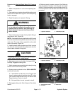
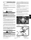
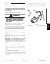
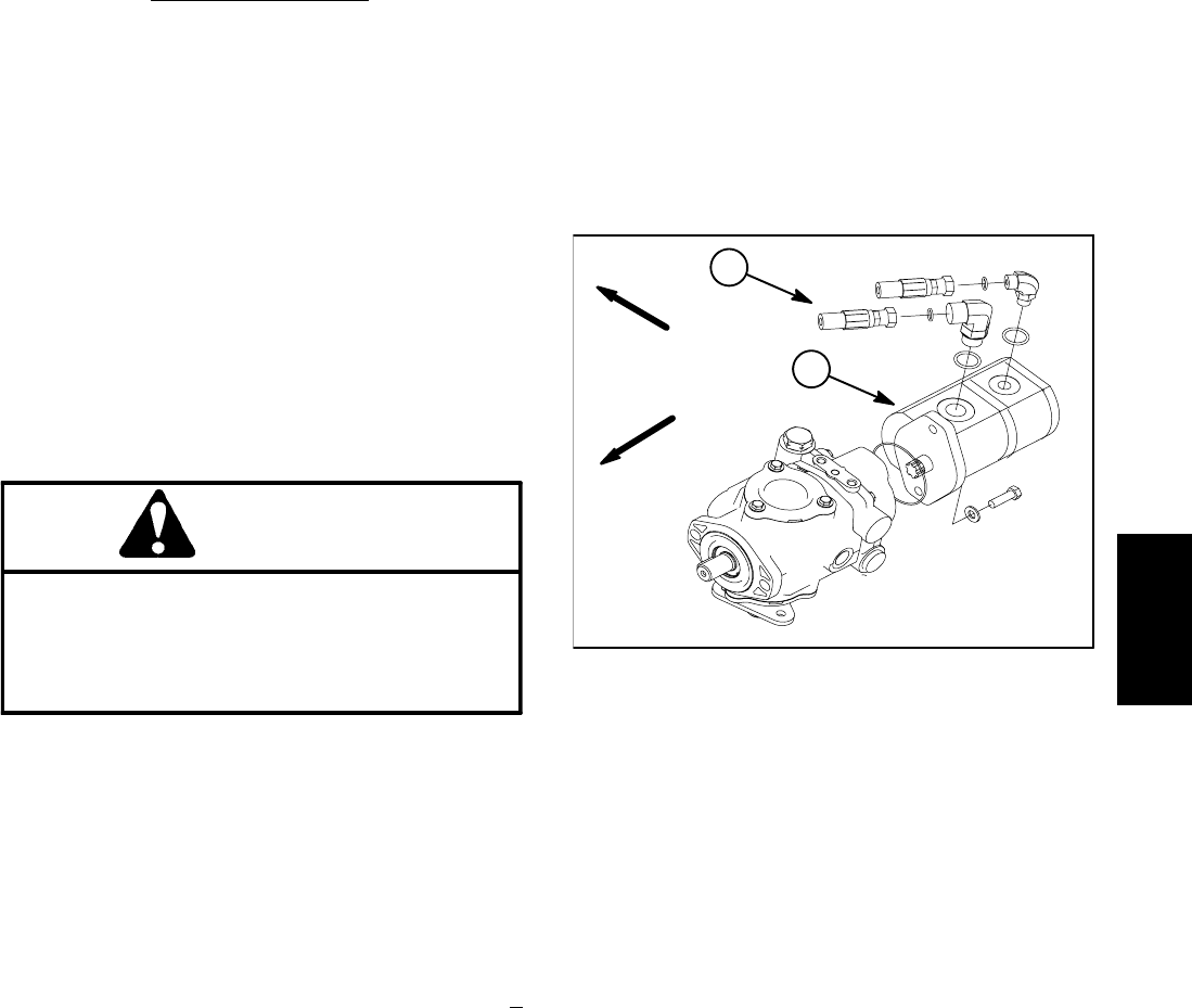
4. Disconnect hose connection on the gear pump (P1)
leading to port (P1) on the hydraulic manifold (Fig. 27).
5. Install hydraulic tester (pressure and flow) in series
with the gear pump and the disconnected hose leading
to port (P1) on the hydraulic manifold.
6. Make sure the flow control valve on the tester is fully
open.
7. Start engine and move throttle to full speed (3050 +
50 RPM). Do not engage the cutting units.
IMPORTANT: In this test, the hydraulic tester is
positioned before the manifold relief valve. Pump
damage can occur if the oil flow is fully restricted by
fully closing the tester flow control valve. Do not
close tester valve fully when performing test.
8. Watch tester pressure gauge carefully while slowly
closing the flow control valve until 2000 PSI is obtained.
Do notclose tester loadvalve fully.Verify witha phototac
that the pump speed is 3100 RPM while maintaining
2000 PSI.
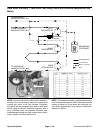
9. Flow indication should be 11.8 GPM minimum.
10.Shut off engine. Record test results.
11.If flow was less than 11.8 GPM or a pressure of 2000
PSIcannot beobtained, checkfor restrictionin thepump
intake line. If line is not restricted, remove gear pump
(P1) and repair or replace as necessary.
12.Relieve hydraulic system pressure (See Relieving
Hydraulic System Pressure in the General Information
section). Disconnect tester from gear pump fitting and
hose. Reconnect hose to the pump.
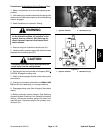
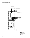
1. Gear pump (P1) 2. To hydraulic manifold
Figure 27
FRONT
RIGHT
1
2
Hydraulic
System