


Groundsmaster 3505--D Page 5 -- 9 Electrical System
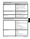
Component Testing
For accurate resistance and/or continuity checks, elec-
trically disconnect the component being tested from the
circuit ( e.g. unplug the ignition switch connector before
doing a continuity check on the switch).
NOTE: For engine component testing information, see
the Kubota Workshop Manual, Diesel Engine, 05 Se-
ries.
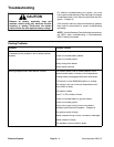
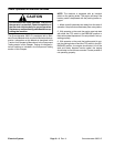
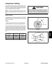
CAUTION
When testing electrical components for continu-
ity with a multimeter (ohms setting), make sure
that power to the circuit has been disconnected.
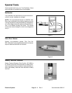
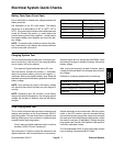
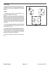
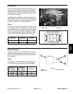
Ignition Switch
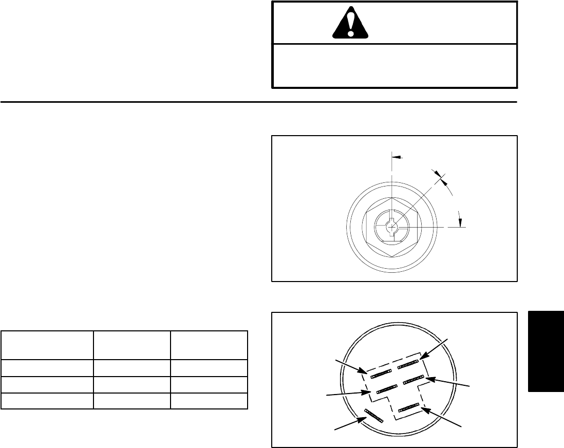
The ignition (key) switch has three positions: OFF, RUN
and START (Fig. 5). The switch terminals are identified
as shown in Figure 6.
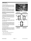
Testing
1. Make sure ignition switch is in the OFF position. Dis-
connect wire harness c onnector from ignition switch.
2. The circuitry of the ignition switch is shown in the
chart below. With the use of a multimeter (ohmss etting),
the switchfunctions maybe testedto determine whether
continuity exists between the various terminals for each
switch position. Verify continuity between switch termi-
nals.
SWITCH
POSITION
NORMAL
CIRCUITS
OTHER
CIRCUITS
OFF NONE NONE
RUN B+A+I X+Y
START B+S+I NONE
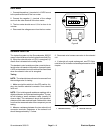
Figure 5
45
°
45
°
RUN
START
OFF
Figure 6
A
B
S
Y
X
I
Electrical
System