


Groundsmaster 3505--DHydraulic System Page 4 -- 86
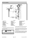
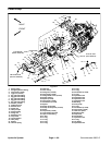
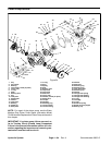
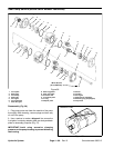
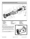
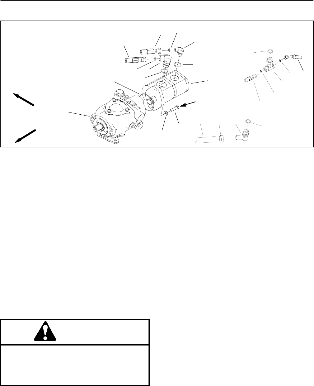
Gear Pump
1. Piston pump
2. Gear pump
3. Hydraulic hose (tank suction)
4. Hydraulic hose (hydraulic manifold)
5. Hydraulic hose (steering valve)
6. Hose clamp
7. Hydraulic barb fitting
8. O--ring
9. O--ring
10. 90
o
hydraulic fitting
11. O--ring
12. O--ring
13. 90
o
hydraulic fitting
14. O--ring
15. Cap screw (2 used)
16. Flat washer (2 used)
17. O--ring
18. Hydraulic hose (reservoir)
19. O--ring
20. Tee fitting
21. Hydraulic hose (oil filter)
Figure 55
1
16
5
10
15
12
13
2
14
4
9
17
11
27 to 31 ft--lb
(37to42N--m)
FRONT
RIGHT
8
18
19
20
21
19
7
8
6
3
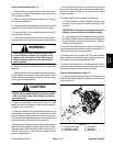
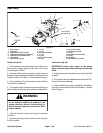
Removal (Fig. 55)
1. Park machine on a level surface, lower cutting units,
stop engine, engage parking brake and remove key
from the ignition switch.
2. Remove muffler from the engine to gain access to
the gear pump (see Muffler Removal in the Service and
Repairs section of Chapter 3 -- Kubota Diesel Engine).
3. Drain hydraulic oil from hydraulic tank (see Traction
Unit Operator’s Manual).
4. Thoroughly clean hydraulichose ends and fittingson
gear pump to prevent hydraulic system contamination.
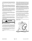
WARNING
Before disconnecting or performing any work
on the hydraulic system, all pressure in the
system must be relieved. See Relieving Hy-
draulic System Pressure in the General Infor -
mation section.
5. Label all hydraulic hoses and fittings for assembly
purposes.
6. Remove gear pump from the piston pump using Fig-
ure 55 as guide.
Installation (Fig. 55)
IMPORTANT: Position gear pump to the piston
pump so that the gear pump suction port is facing
down.
1. Install gear pump to the piston pump using Figure 55
as guide.
2. Fill hydraulic tank with new hydraulic fluid (see Trac-
tion Unit Operator’s Manual).
3. Install muffler to the engine (see Muffler Installation
in theService andRepairs sectionof Chapter3 -- Kubota
Diesel Engine).