


Rev. A
Groundsmaster 3505--D Page 7 -- 13 Cutting Units
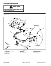
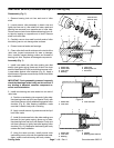
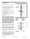
Installation (Fig. 13)
1. Place spindle plate on cutting deck making sure to
align notches in plate and cutting deck.
2. Position spindlehousing to underside of cuttingdeck
making sure that grease fitting is toward the front of the
deck.
3. Secure spindle housing and spindle plate to cutting
deck with six (6) cap screws and flange nuts.
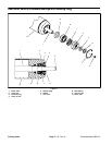
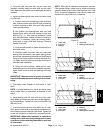
4. Install cutting blade, anti--scalp cup and bolt (see
Cutting UnitOperator’s Manual).Tighten bladebolt from
88 to 108 ft--lb (119 to 146 N--m).
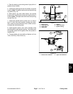
5. Position O--ring to top of spindle housing.
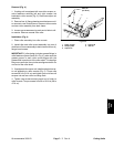
6. Position hydraulic deckmotor to cutting deck making
sure to align motor shaft splines with spindle shaft
splines.
7. Secure hydraulic deck motor to the cutting unit with
two (2) socket head screws and flat washers.
IMPORTANT: When greasing spindles on the
Groundsmaster 3505--D, grease passes into the
center of the spindle shaft and out to fill the bearing
cavity of the housing. If grease does not come out
of lower seal when greasing, check lubrication hole
in spindle shaft for obstruction.
NOTE: Pneumatic grease guns can produce air pock-
ets when filling large cavities. U se a hand pump grease
gun when adding grease to spindle housing.
8. Using a hand pump grease gun, fill spindle housing
cavity with grease until grease starts to come out of low-
er seal.
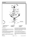
1. Hydraulic deck motor 2. Socket head screw
Figure 14
2
1
2
Cutting
Units