Groundsmaster 3505--D Page 5 -- 11 Electrical System
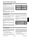
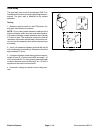
Hour Meter
1. Connect the positive (+) terminal of a 12 VDC source
to the positive terminal of the hour meter.
2. Connect the negative (--) terminal of the voltage
source to the other terminal of the hour meter.
3. The hour meter should move 1/10 of an hour in six
minutes.
4. Disconnect the voltage source from the hour meter.
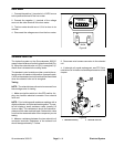
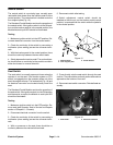
Figure 8
QUARTZ
Hobbs
HOURS
1
0000
1
10
+
BACK
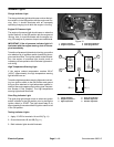
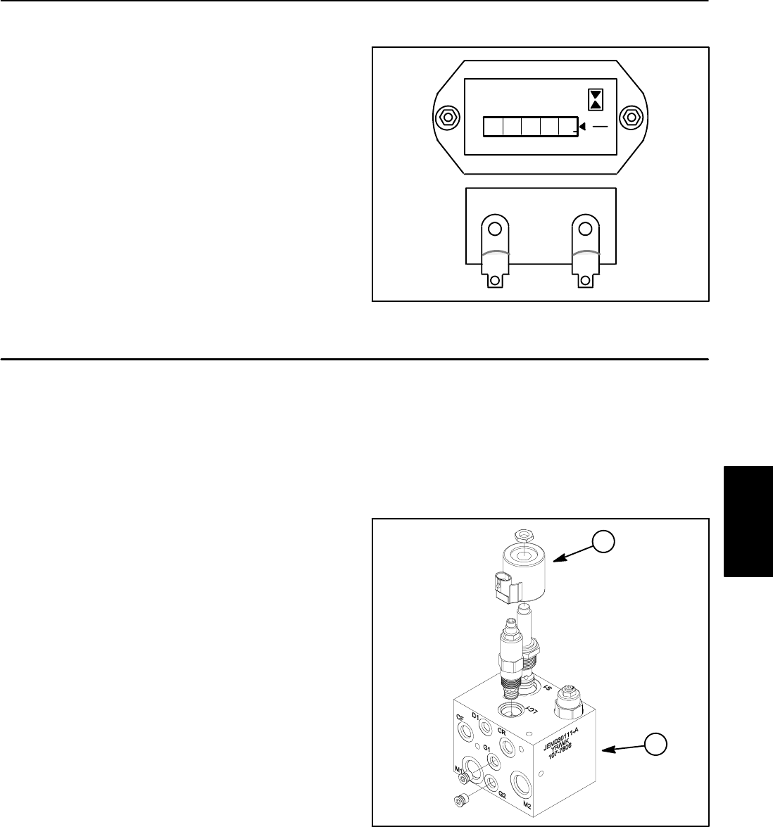
Solenoid Valve Coil
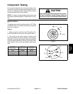
The hydraulic system on the Groundsmaster 3505--D
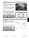
uses asolenoid valve coil onthe hydraulic manifold(Fig.
9). When the s olenoid valve coil (R1) is energized, hy-
draulic flow is directed to the cutting decks.
The standard control module provides current to the so-
lenoid valve coil based on the position of several inputs.
A LEDon the standardcontrol module willbe illuminated
when the solenoid valve coil is energized.
Testing
NOTE: Thes olenoid does not have to be removedfrom
the cartridge valve for testing.
1. Make sure ignition switch is in the OFF position. Un-
plug wire harness electrical connector from solenoid
valve coil.
NOTE: Prior to taking small resistance readings with a
digital multimeter, short the test leads together. The me-
ter will display a small resistance value (usually 0.5
ohms or less). This resistance is due to the internal re-
sistance of the meter and test leads. Subtract this value
from from themeasured value of the componentyou are
testing.
2. Measure resistance between the two solenoid coil
connector terminals. Resistance of the solenoid coil
should be approximately 7.5 ohms.
3. Reconnect w ire harness connector to the solenoid
coil.
4. If solenoid coil needs replacement, see PTO Sole-
noid Valve Coil in the Service and Repairssection of this
chapter.
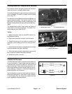
1. Manifold assembly 2. Solenoid valve coil
Figure 9
2
1
Electrical
System


