Groundsmaster 3505--DPage 5 -- 10Electrical System
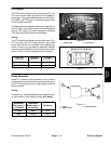
Glow Relay
The glow relay used on the Groundsmaster 3505--D al-
lows electricalcurrent tothe engineglow plugs whenen-
ergized. The glow relay is attached to the radiator
assembly.
Testing
1. Make sure ignition switch is in the OFF position. Un-
plug glow relay electrical connector.
NOTE: Prior to taking small resistance readings with a
digital multimeter, short the meter test leads together.
The meter will display a small resistance value (usually
0.5 ohms or less). This resistance is due to the internal
resistance of the meter and test leads. Subtract this val-
ue from from the measured value of the component you
are testing.
2. Verify coil resistance between terminals 85 and 86
with a multimeter (ohms setting). Resistance should be
approximately 72 ohms.
3. Connect multimeter (ohmssetting) leads to relay ter-
minals 30 and 87. Ground terminal 86 and apply +12
VDC to terminal 85. The relay should make and break
continuity between terminals 30 and 87 as +12 VDC is
applied and removed from terminal 85.
4. Disconnect voltage and leads from the relay termi-
nals.
Figure 7
86 87
85 30
85 86
87
30


