


Groundsmaster 3505--D Page 6 -- 11 Chassis
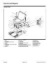
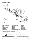
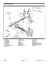
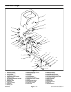
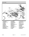
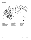
Disassembly (Fig. 7)
1. Park machine on a level surface, lower cutting units,
stop engine, engage parking brake and remove key
from the ignition switch.
2. Remove hood from the machine (see Traction Unit
Operator’s Manual).
WARNING
Before jacking upthe machine, reviewand follow
Jacking Instructions in Chapter 1 -- Safety.
3. Chockfront wheels. Jackup rear wheelenough to al-
low the removal of the rear fork. Support machine with
jack stands or blocking.
4. Remove lug nuts from rear wheel drive studs. Re-
move rear wheel assembly from machine.
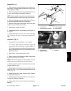
5. Separate hydraulic steering cylinder from the rear
fork as follows:
A. Remove both jam nuts securing the ball joint to
the rear fork.
B. Separate ball joint from the rear fork.
C. Swing steering cylinder clear of the rear fork.
6. Remove dust cap from hub. Remove cotter pin, nut
retainer, jam nut and tab washer to allow removal of
wheel hub and bearings. Pull wheel hub with bearings
and seal from machine.
7. If necessary, remove seal and bearings from wheel
hub.
8. Inspect bearing cups in wheel hub for wear or dam-
age. If bearing c ups are damaged, replace the wheel
hub.
CAUTION
Support rear fork to prevent its falling during re-
moval and installation. Personal injury or dam-
age to the fork may result from improper han-
dling.
9. Remove cap screw, thrust washer and lock washer
from the rear fork shaft. Slide rear fork from machine.
10.Check flange bushings in rear casting for wear or
damage. Replace bushings if necessary.
Assembly (Fig. 7)
1. Position rear fork through the frame.
2. Install lock washer, thrust washer and cap screw to
the rear fork shaft. Torque cap screw from 60 to 80 ft--lb
(81 to 108 N--m). Make sure fork turns freely after cap
screw has been tightened.
3. If seal and inner bearing were r emoved from the
wheel hub, place greased bearing c one into inner bear-
ing cup. Install new seal.
4. Slidew heel hub onto machine.Position greased out-
er bearing and tab washer onto shaft.
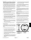
5. Install jam nut onto shaft and tighten fully to seat
bearings. Backoff jamnut andthen, while rotatingwheel
hub, torque nut from 15 to 20 in--lb (1.7 to 2.3 N--m).
6. Install nut retainer, cotter pin and dust c ap.
7. Secure hydraulic steering cylinder to the rear fork as
follows:
A. Swing steering cylinder to the rear fork.
B. Install ball joint to rear fork.
C. Secure ball joint to rear fork with two (2) jam nuts.
Tighten the first jam nut from 65 to 85 ft--lb (88 to 115
N--m), then tighten the second jam nut to the same
specification.
8. Secure wheel assembly to the wheel hub with four
(4) lug nuts.
9. Lower machine to the ground. Torque lug nuts in a
crossing pattern from 45 to 65 ft--lb (61 to 88 N--m).
10.Lubricate grease fittings (see Traction Unit Opera-
tor’s Manual).
Chassis