


Groundsmaster 3505--D Hydraulic SystemPage 4 -- 103
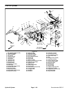
Removal (Fig. 68)
1. Park machine on a level surface, lower cutting units,
stop engine, engage parking brake and remove key
from the ignition switch.
NOTE: Therear tire mustbe removed to allowsufficient
clearance to remove the steering cylinder from the ma-
chine.
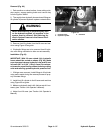
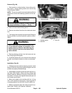
WARNING
Before jacking upthe machine, reviewand follow
Jacking Instructions in Chapter 1 -- Safety.
2. Jack or lift rear wheel off the ground.
3. Remove rear wheel from the drive studs and wheel
hub.
4. Thoroughly clean hydraulichose ends and fittingson
steering cylinder to prevent hydraulic system contami-
nation.
WARNING
Before disconnecting or performing any work
on the hydraulic system, all pressure in the
system must be relieved. See Relieving Hy-
draulic System Pressure in the General Infor -
mation section.
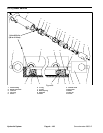
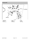
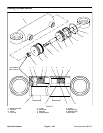
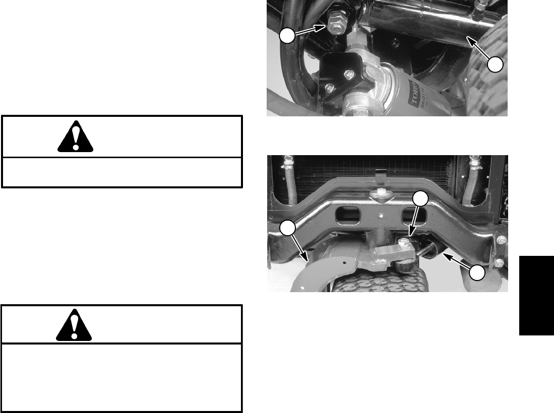
5. Remove steering cylinder from the frame and rear
fork using Figure 68 as guide.
6. If hydraulic fittings are to be removed from steering
cylinder, mark fitting orientation to allow correct assem-
bly.
Installation (Fig. 68)
1. If fittings were removed from steering cylinder, install
fittings to cylinder using marks made during the removal
process to properly orientate fittings.
2. Install steering cylinder to the frame and rear fork us-
ing Figure 68 as guide. When securing cylinder ball
joints to machine, tighten the first jam nut from 65 to 85
ft--lb (88 to 115 N--m), then tighten the second jam nut
to the same specification.
3. Mount rear wheel to the machine with four (4) lug
nuts. Lower machine to the ground. Torque lug nuts in
a crossing pattern from 45 to 65 ft--lb (61 to 88 N--m).
4. Make surehydraulic tank is full. Add correct oilif nec-
essary (see Traction Unit Operator’s Manual).
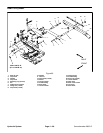
1. Steering cylinder 2. Jam nuts
Figure 69
1
2
1. Steering cylinder
2. Rear fork
3. Jam nuts
Figure 70
2
3
1
Hydraulic
System