


Groundsmaster 4100--D/4110--D Hydraulic SystemPage 4 -- 45
Procedure for Counterbalance Pressure
Test
CAUTION
Prevent personal injury and/or damage to equip-
ment. Read all WARNINGS, CAUTIONS and Pre-
cautions for Hydraulic Testing at the beginning
of this section.
1. Park machine on a level surface with the cutting deck
lowered and off. Make sure hydraulic oil is at normal op-
erating temperature, engine is off and the parking brake
is applied.
2. Raise and support operator seat to gain access to
combination manifold.
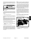
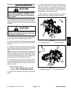
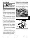
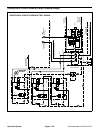
3. Connect a 1000 PSI (70 bar) pressure gauge to test
port G1 on combination manifold (Fig. 30).
NOTE: The cutting deck need to be in the float position
when checking counterbalance pressure. Also, make
sure that all of the cutting deck castor wheels are on the
ground when testing or adjusting counterbalance pres-
sure.
IMPORTANT: While testing counterbalance pres-
sure, DO NOT raise the cutting deck. If deck is
raised, system pressure increase will damage pres-
sure gauge.
4. Start engine and increase engine speed to high idle
speed with no load on the hydraulic system. Do not en-
gage the cutting deck.
GAUGE READING TO BE approximately 325 PSI
(22.4 bar).
NOTE: The recommended counterbalance pressure is
325 PSI (22.4 bar).
5. Stop engine and record test results.
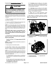
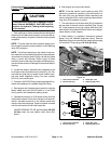
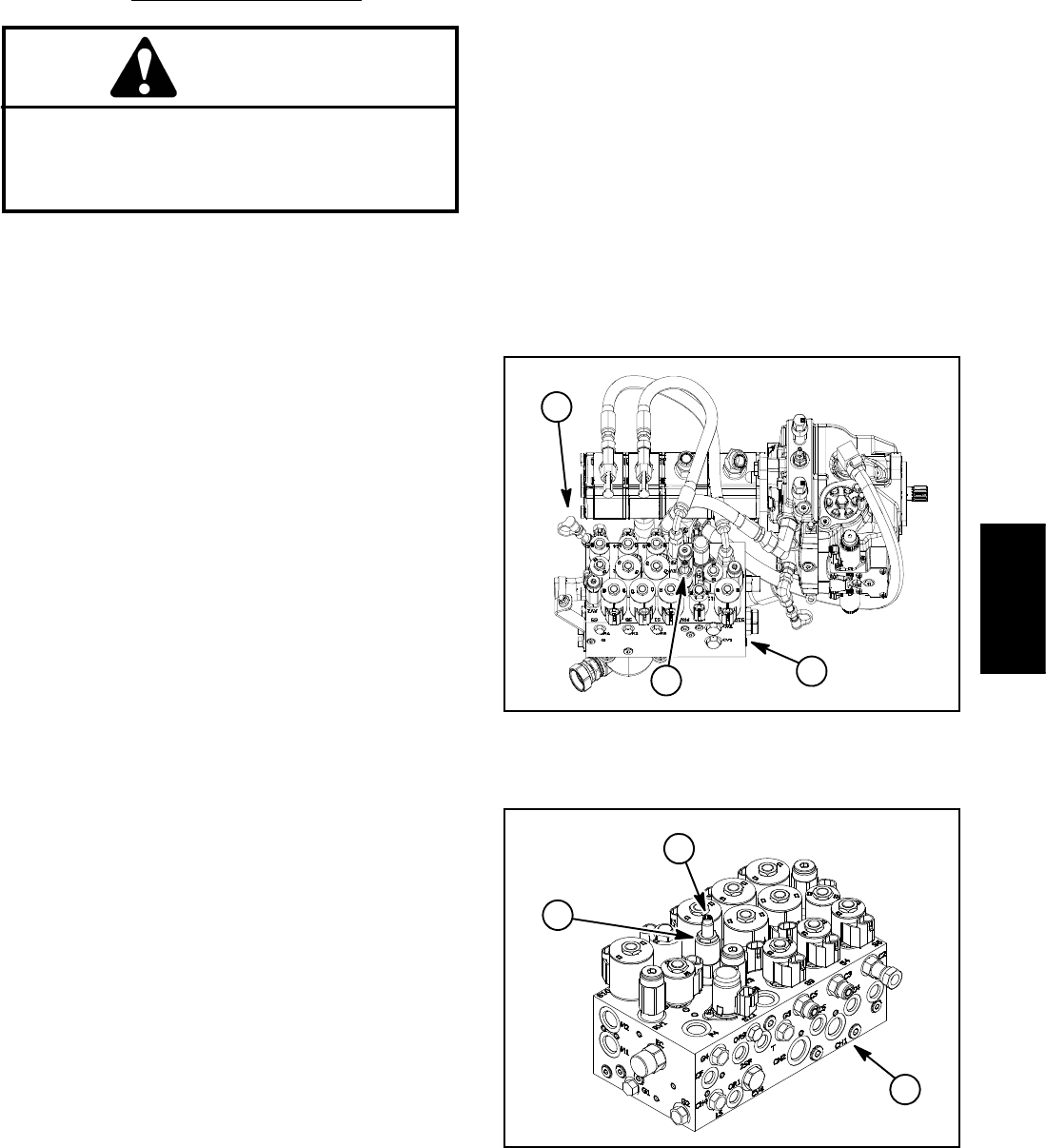
6. The pressure reducing valve on the combination
manifold is used to set the counterbalance pressure
(Fig. 31). If necessary, adjust pressure reducing valve:
NOTE: Because of valve design, the pressure reducing
valve can be adjusted with the engine running. Do not
remove the pressure reducing valve from the hydraulic
manifold for adjustment.
A. Locate pressure reducing valve on combination
manifold (Fig. 31). Loosen lock nuton pressure redu-
cing valve.
B. Start engine and increase engine speed to high
idle speed with no load on the hydraulic system. Do
not engage the cutting deck.
C. To increase pressure setting, turn the adjust-
ment screw on the valve in a clockwise direction. A
1/8 turn on the screw willmake ameasurable change
in counterbalance pressure.
D. To decrease pressure setting, turn the adjust-
ment screw on the valve in a counterclockwise direc-
tion. A 1/8 turn on the screw will make a measurable
change in counterbalance pressure.
E. Tighten lock nut to secure adjustment. Check
counterbalance pressure and readjust as needed.
7. When testing is completed, disconnect pressure
gauge from manifold test port. Secure dust cap to test
fitting. Lower operator seat.
1. Combination manifold
2. Test port G1
3. Pressure reducing valve
Figure 30
2
1
3
1. Combination manifold
2. Pressure reducing valve
3. Adjustment screw
Figure 31
2
3
1
Hydraulic
System