Groundsmaster 4100--D/4110--DHydraulic System Page 4 -- 68
Adjustments
Adjust Control Manifold Relief Valves
Several of the hydraulic control manifolds on the
Groundsmaster include adjustable relief valves. Thefol-
lowing procedure can be used to adjust these relief
valves. Refer to the Testing section of this chapter for in-
formation on testing relief pressure.
NOTE: Do not remove relief valve from the hydraulic
manifold for adjustment.
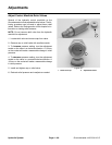
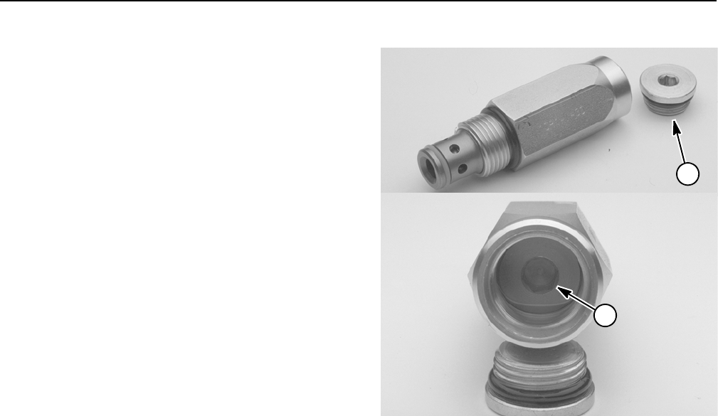
1. Locate relief valve and remove cap from valve.
2. Remove cap on relief valve with an allen wrench.
3. To increase pressure setting, turn the adjustment
socket on the valve in a clockwise direction. A 1/8 turn
on the socket will make a measurable change in relief
pressure.
4. To decrease pressure setting, turn the adjustment
socket on the valve in a counterclockwise direction. A
1/8 turn on the socket will make a measurable change
in relief pressure.
5. Install and tighten cap on relief valve.
6. Recheck relief pressure and readjust as needed.
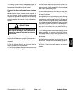
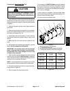
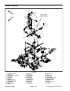
Figure 49
1. Relief valve cap 2. Adjustment socket
1
2


