


Groundsmaster 4100--D/4110--D Hydraulic SystemPage 4 -- 105
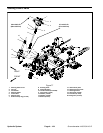
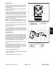
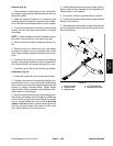
Removal (Fig. 77)
1. Park machine on a level surface, lower cutting deck,
stop engine, apply parking brake and remove key from
the ignition switch.
2. Remove steering tower cover to allow access to
steering control valve.
3. Read the General Precautions for Removing and
Installing Hydraulic System Components at the begin-
ning of the Service and Repairs section of this chapter.
4. To prevent contamination of hydraulic system during
steering control valve removal, thoroughly clean exteri-
or of control valve and fittings.
NOTE: To ease installation, label the hydraulic lines to
show their correct position on the steering control valve.
5. Remove hydraulic lines from steering control valve.
6. Remove steering control valve from machine using
Figure 77 as a guide.
7. If hydraulic fittings are to be removed from steering
control valve, mark fitting orientation to allow correct as-
sembly. Remove fittings from valve and discard O--rings
(Figs. 78 and 79).
Installation (Fig. 77)
1. If fittings were removed from steering control valve,
lubricate and place new O--rings onto fittings. Install fit-
tings into p ort openings using marks made during there-
moval process toproperly orientate fittings (Figs. 78a nd
79). Tighten fittings (see Hydraulic Fitting Installation in
the General Information section of this chapter).
2. Install steering control valve using Figure 77 as a
guide.
3. Using labels placed during steering control valve re-
moval, properly install hydraulic lines to control valve
(see Hydraulic Hose and Tube Installation in the Gener-
al Information section of this chapter).
4. Make sure hydraulic tank is full.
5. Properly fill hydraulic system (see Charge Hydraulic
System in this section).
6. Install steering tower cover to machine.
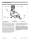
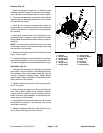
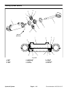
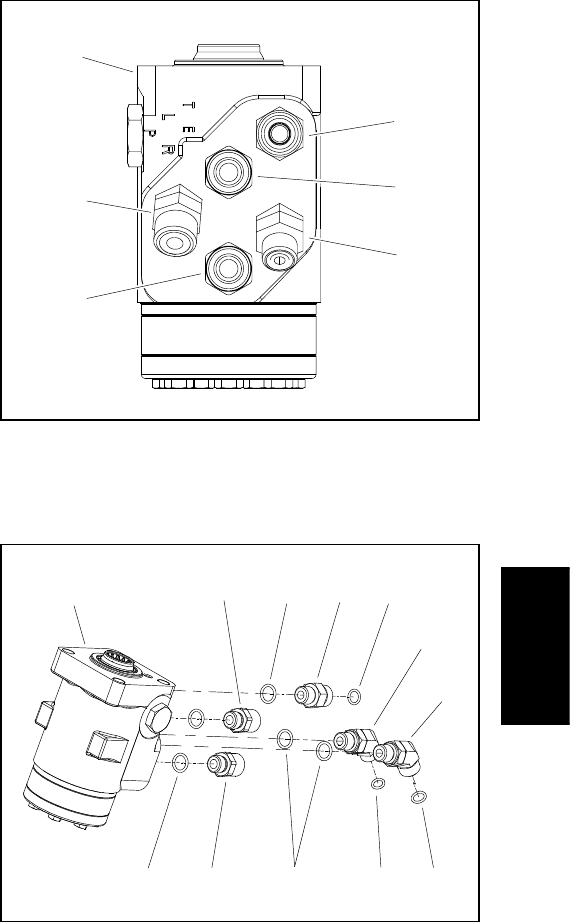
1. Steering control valve
2. 45
o
hydraulic fitting
3. Straight fitting (2 used)
4. 45
o
hydraulic fitting
5. Straight fitting
Figure 78
1
2
4
5
3
3
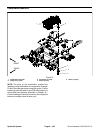
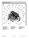
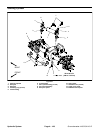
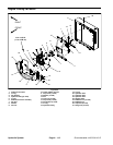
1. Steering control valve
2. O--ring
3. Straight fitting
4. Straight fitting
5. 45
o
fitting
6. 45
o
fitting
7. O--ring
8. O--ring
Figure 79
1
2
4
5
32
23
6
7
7
8
Hydraulic
System