


Groundsmaster 4100--D/4110--D Cutting DeckPage 8 -- 17
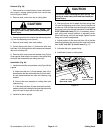
Installation (Fig. 13)
1. If screws were removed from spindle housing, press
new screws into housing. Make sure that screw head is
squarely seated against housing after installation.
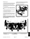
2. Position spindle on cutting deck noting orientation of
grease fitting (Fig.15). Secure spindle assembly to deck
with removed fasteners.
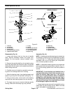
3. Install cutting blade, anti--scalp cup and blade bolt.
Tighten blade bolt from 88to108ft--lb(119to146
N--m).
4. Slowly rotate cutting blades to verify that blades do
not contact any deck component(s).
5. Install drive belt and adjust belt tension (see Idler As-
sembly Installation in this section).
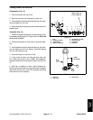
6. If drive spindle was removed, install hydraulic motor
to cutting deck (see Cutting Deck Motor Installation in
the Service and Repairs Section of Chapter 4 -- Hydrau-
lic System).
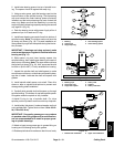
IMPORTANT: Pneumatic grease guns can produce
air pockets w hen filling large cavities and therefore,
are not recommended to be used for proper greas -
ing of spindle housings.
7. Attach a hand pump grease gun to grease fitting on
spindle housing and fill housing cavity with grease until
grease starts to come out of lower seal.
8. Install belt covers to cutting deck.
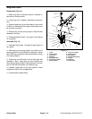
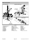
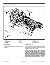
1. Hydraulic motor 2. Flange head screw
Figure 14
1
2
2
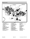
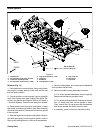
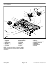
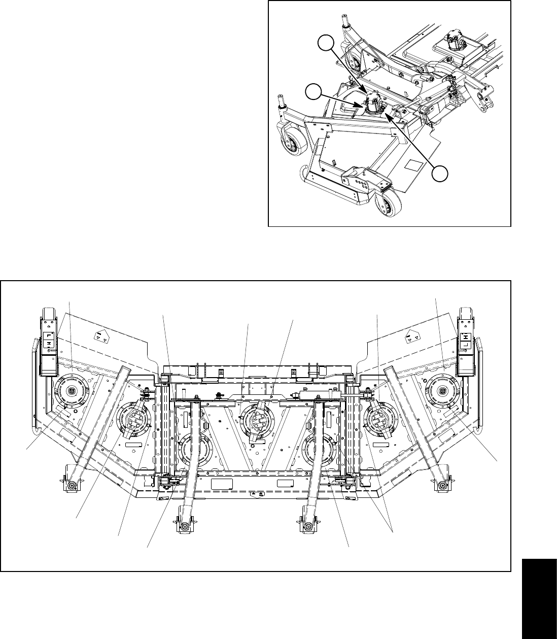
1. Driven spindle
2. Driven spindle (high pulley)
3. Drive spindle (wing deck)
4. Drive spindle (center deck)
5. Spindle grease fitting location
Figure 15
5
3
2
5
1
1
4
3
5
1
5
5
5
Cutting
Deck