


Groundsmaster 4100--D/4110--DPage 5 -- 46Electrical System
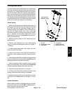
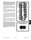
Relays with Four (4) Terminals
Your Groundsmaster uses a number of electrical relays
that have four (4) terminals. A tag near the wire harness
relay connector can be used to identify each relay.
The main power relay is used to provide current to most
of the fuse protected circuits (operator seat, InfoCenter
display, power point and optional electric equipment).
The main power relay is energized when the ignition
switch is in the RUN or START position.
The TEC power relay is used to provide current to the
fuse protected circuits for the TEC controller. The TEC
power relay is energized when the ignition switch is in
the RUN or START position.
The cab power r elay is used on Groundsmaster 4110--D
machines to provide current to the operator cab electri-
cal components. The cab power relay is energized when
theignitionswitchisintheRUNorSTARTposition.
The start relay is used to provide current to the engine
starter motor solenoid. The start relay is energized by
the engine ECU.
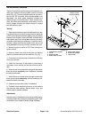
The air heater relay is used on models 30602 and 30604
to provide current for the engine air heater used forstart-
ing a cold engine. When necessary, the air heater relay
is energized by the engine ECU.
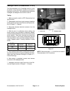
The glow relay is used on models 30606 and 30608 to
provide current to the engine glow p lugs when ener-
gized by the engine ECU.
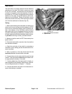
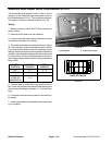
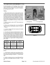
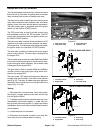
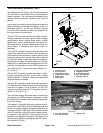
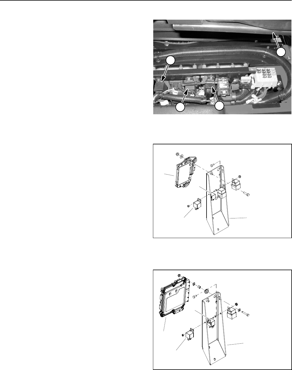
The main power, TEC power and cab power relays are
located under the controller cover next to the operator
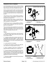
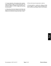
seat (Fig. 56). The start, air heater and glow relays are
attached to the controller mount on the right side of the
engine (Fig. 57 or 58).
Testing
1. Parkmachineonalevelsurface, lower cutting deck,
stop engine, engage parking brake and remove key
from the ignition switch.
2. To make sure that machine operation does not occur
unexpectedly, disconnect negative (--) cable from bat-
tery and then disconnect positive (+) cable from battery
(see Battery Service in the Service and Repairs section
of this chapter).
3. Locate relay that is to be tested.
4. Disconnect wire harness connector from relay. Re-
move relay from mounting bracket for testing.
1. Main power relay
2. TEC power relay
3. Cab power relay
4. Operator seat
Figure 56
1
2
4
3
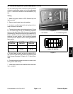
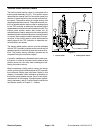
1. Controller mount
2. Engine ECU
3. Start relay
4. Airheaterrelay
Figure 57
MODELS 30602 AND 30604
1
3
2
4
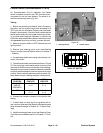
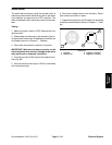
1. Controller mount
2. Engine ECU
3. Start relay
4. Glow relay
Figure 58
MODELS 30606 AND 30608
2
3
1
4