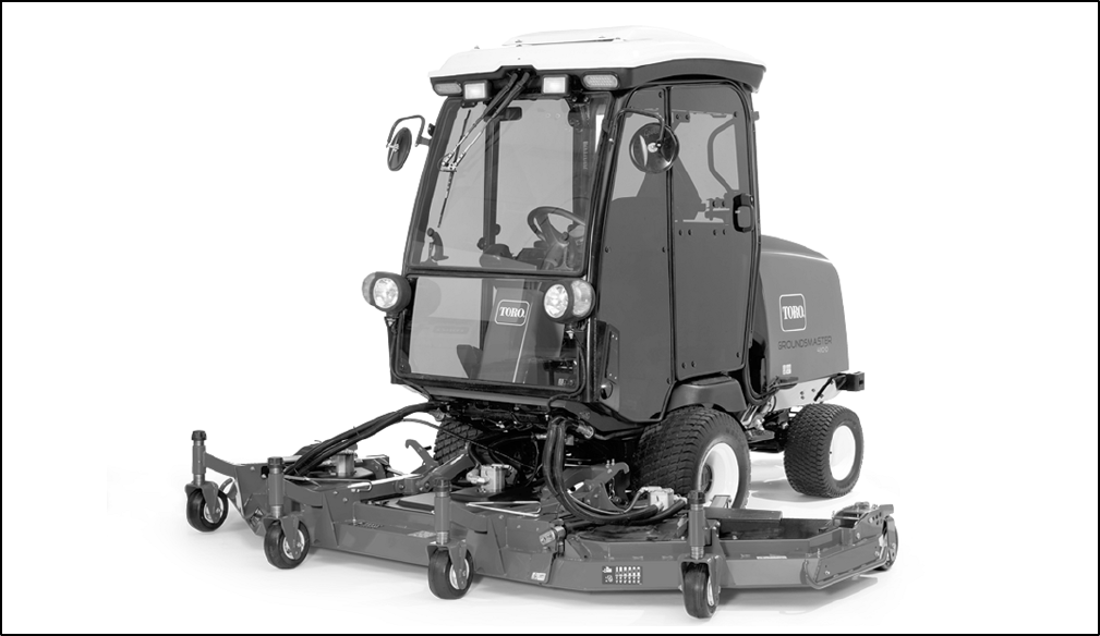
Groundsmaster 4100--D/4110--DCutting Deck
Page 8 -- 2
Specifications
MOUNTING: Cutting deck is supported by lift arms con-
trolled with individual lift switches for complete deck,
right wing deck and left wing deck.
CONSTRUCTION: Deck chamber is welded 12 gauge
steel construction reinforced with channels and plates.
HEIGHT--OF--CUT RANGE: 1” to 5” (25.4 mm to 127
mm) adjustable in 1/2” (12.7 mm) increments. Center
deck height--of--cut adjustment is achieved by changing
spacers on castor wheels a nd adjusting length of deck
support chains. Wing deck adjustment is achieved by
changing spacers on castor wheels, re--positioning the
castor wheel a xles in the castor forks and securing the
castor wheel bracket to the correct height--of--cut brack-
et holes.
DECK DRIVE: Closed loop hydraulic system operates
hydraulic motor on each cutting deck section. Motor
drives one deck spindle directly with remaining deck
section spindle(s) driven by B section kevlar v--belt(s).
Blade spindles are 1--1/4” (31.7 mm) shafts supported
by greaseable, tapered roller bearings.
CUTTING BLADE: Cutting blade dimensions are 19”
(483 mm) long, 2.5” (64 mm) wide and 0.250” (6.4 mm)
thick. Anti--scalp cup installed on each cutting blade.
Center deck includes three (3) blades and each wing
deck includes two (2) blades.
WIDTH OF CUT: Center deck section provides 54”
(1372 mm) width of cut. Each wing deck has 37” (940
mm) width of cut. Total width of cut is 124” (3150 mm).
DISCHARGE: Clippings are discharged from the rear of
the cutting deck.
SUSPENSION SYSTEM: A fully floating suspension
with hydraulic counterbalance. Front deck is suspended
from lift arms and has six (6) castor wheels, two ( 2) ad-
justable skids and five (5) anti--scalp rollers.


