


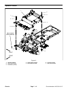
Groundsmaster 4100--D/4110--DPage 7 -- 6Chassis
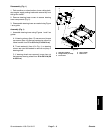
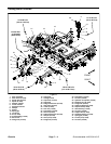
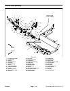
Installation (Fig. 3)
1. If removed, install components t o lift arm.
A. Press flange bushings into lift arm.
B. Install spherical bearing on tapered stud and se-
cure with flange nut. Torque flange nut from 30 to 40
ft--lb(41to54N--m). Install stud with spherical bear-
ing into lift arm and secure with retaining ring.
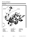
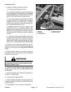
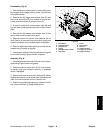
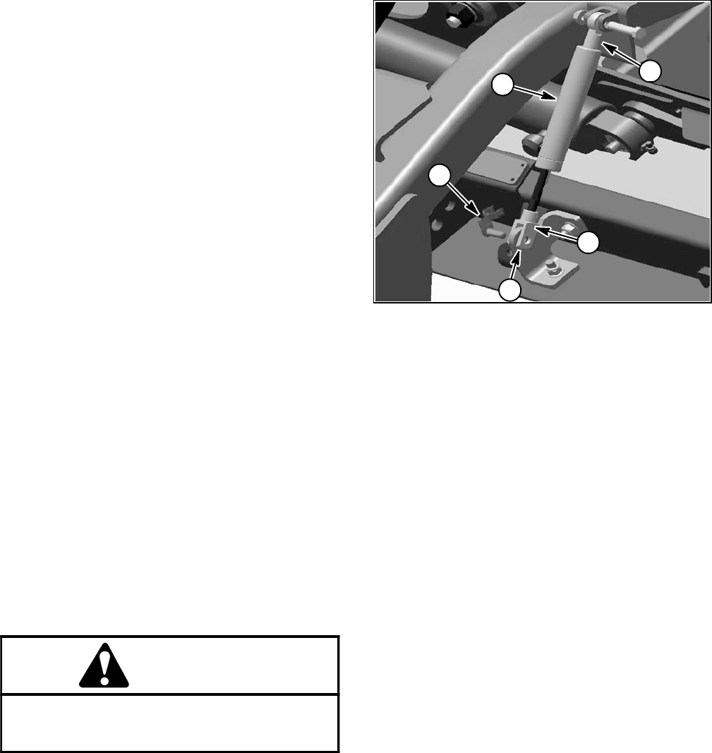
C. If rod and clevis ends were removed from damp-
er, apply Loctite #271 (or equivalent) to threads on
damper shaft and stud. Install ends on damper.
Install damper assembly to lift arm with damper clev-
is end toward deck location (Fig. 7).
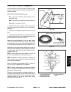
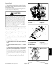
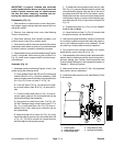
D. Assemble height--of--cut chain u--bolt so that
threaded portion of u--bolt extends 0.750 in. (19.1
mm) above mounting plate on lift arm (Fig. 6). This
dimension is a starting point that might need addi-
tional adjustment for deck pitch correction (see step
8below).
E. Thoroughly clean tapered surfaces of stud and
mounting boss of support hub. Secure support hub
(position slotted hole in hub toward rear of deck) to
tapered stud with flat washer and flange nut. Torque
flange nut from 155 to 185 ft--lb (211 to 251 N--m).
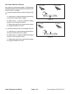
2. Position lift arm to frame and insert lift arm pin. En-
gage roll pin in lift arm pin into frame slots and install lock
nut on pin. Torque lock nut from 60 to 70 ft--lb (82 to 94
N--m).
3. Align lift cylinder with lift arm. Slide lift cylinder pin
through lift arm and cylinder end. Secure pin with flange
head screw and lock nut.
WARNING
Failure to maintain proper wheel lug nut torque
could result in failure or loss of wheel and may
result in personal i njury.
4. Install front wheel assembly. Lower machine to the
ground. Torque wheel lug nuts from 85 to 100 ft--lb (115
to 135 N--m).
5. Install cutting deck (see Cutting Deck Installation in
Chapter 8 -- Cutting Deck).
6. Lubricate lift arm grease fittings.
7. After assembly is completed, raise and lower the cut-
ting deck to verify that hydraulic hoses and fittings donot
contact anything.
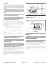
8. Check height--of--cut and deck pitch adjustment.
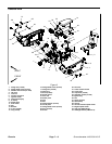
1. Damper
2. Spring pin
3. Damper rod end
4. Damper clevis end
5. Spacer location
Figure 7
1
3
4
2
5