


Groundsmaster 4100--D/4110--D Page 5 -- 45 Electrical System
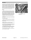
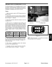
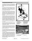
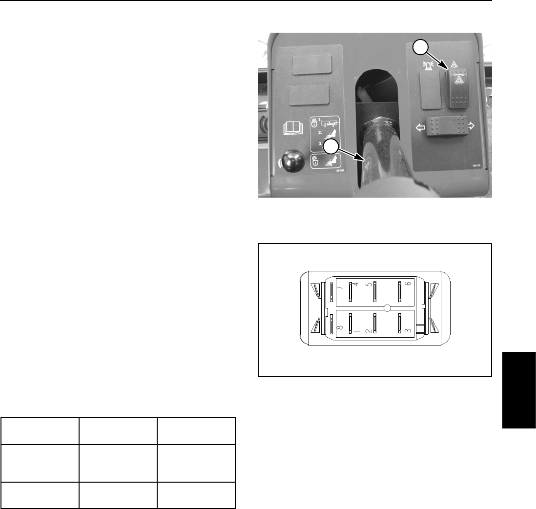
Flasher Switch (Groundsmaster 4110--D)
On Groundsmaster 4110--D machines, the flasher
switch is used as an input for the TEC controller to pro-
vide power for the four way flashers. The switch is lo-
cated o n the steering tower (Fig. 54).
Testing
1. Before disconnecting the flasher switch for testing,
the switch and its circuit wiring should be tested as a
TEC input with the InfoCenter Display (see InfoCenter
Display in this chapter). If the InfoCenter verifies that the
flasher switch and circuit wiring are functioning correct-
ly, no further switch testing is necessary. If, however, the
InfoCenter determines that the flasher switch and circuit
wiring are not functioning correctly, proceed with test.
2. Make sure ignition switch is OFF. Remove key from
ignition switch.
3. Remove front steering tower cover (see Steering
Tower in the Service and Repairs section of Chapter 7
-- Chassis).
4. Locate flasher switch and unplug wire harness con-
nector from switch.
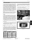
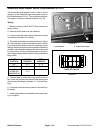
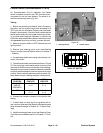
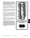
5. The switch terminals are marked as shown in Figure
55. The circuit logic of the flasher switch is shown in the
chart below. With the use of a multimeter (ohms setting),
theswitchfunctionsmaybetestedtodeterminewhether
continuity exists between the various terminals for each
position. Verify continuity between switch terminals. Re-
place flasher switch if testing identifies a faulty switch.
SWITCH
POSITION
CLOSED
CIRCUITS
OPEN
CIRCUITS
ON (LIGHT
END DE-
PRESSED)
2+3
5+6
2+1
5+4
OFF 2+1
5+4
2+3
5+6
6. Connect the harness connector to the switch after
testing.
7. If switch tests correctly and circuit problem still ex-
ists, check wire harness (see Electrical Schematics and
Wire Harness Drawings in Chapter 10 -- Foldout Draw-
ings).
8. Install front steering tower cover (see Steering Tower
in the Service and Repairs section of Chapter 7 -- Chas-
sis).
Figure 54
1. Steering column 2. Flasher switch
1
2
Figure 55
BACK OF SWITCH
Electrical
System