


Groundsmaster 4100--D/4110--D Hydraulic SystemPage 4 -- 23
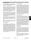
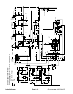
Steering Circuit
A four section gear pump is coupled to the piston (trac-
tion) pump. The fourth gear pump section (farthest from
the piston pump) supplies hydraulic flow to the steering
circuit, the engine cooling fan circuit and the traction
charge circuit. Priority hydraulic flow from this gear
pump section is provided to the steering circuit by the
pressure compensator valve (EC) located in the com-
bination manifold.
NOTE: The hydraulic schematic symbol for the pres-
sure compensatorvalve (EC) appears to be a two (2) po-
sition valve. In operation, this valve will direct the gear
pump section flow to the steering circuit as priority de-
pending on steering input. The remainder of the gear
pump section flow will be directed to the charge and en-
gine cooling fan circuits. If there is no steering input, the
compensator valve (EC) directs all gear pump section
flow to the charge and engine cooling fan circuits.
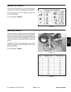
The combination manifold controls the operation of the
steering control valve, the engine cooling fan motor and
the cutting deck lift cylinders. The pressure compensat-
or valve (EC) in the manifold controls the oil flow to the
steering control valve which is a closed center, load
sensing valve. The steering control valve senses the oil
flow that is needed for steering and the compensator
valve (EC) will supply the correct amount. Oil flow not
needed for the steering circuit is provided to the engine
cooling fan motor and then to the traction charge circuit.
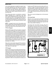
With the steering wheel in the neutral, at rest position
and the engine running, hydraulic oil from the final gear
pump section enters the combination manifold port P4,
flows through the pressure compensator valve (EC) and
to the steering control valve where it dead heads at the
steering control spool. Oil is also sent to both ends of the
compensator valve (EC) spool. On one end of the spool,
oil is directed to the steering relief valve (RV1) and also
is directed through the OR1 orifice and out the LS man-
ifold port to the steering control valve. This flow provides
steering load sense pressure and is directed through a
small passage in the steering control valve spool and
sleeve before returning to the hydraulic reservoir. While
this load sense pressure is returning to the reservoir, the
compensator valve (EC) spool shifts to direct pump flow
to the engine cooling fan motor circuit and then to the
traction charge circuit. Without steering input, no oil is
flowing t hrough the steering control valve to the steering
cylinder.
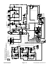
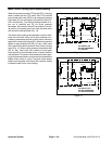
Right Turn
When a right turn is made with the engine running, the
turning of the steering wheel positions the steering con-
trol valve spool so thatthe load sense flow is blocked off.
Without load sense flow, pressures on the ends of man-
ifold compensator valve (EC) start to equalize causing
(EC) to movetoward its neutral position which allows the
needed oil flow to the steering control valve. Oil is routed
out manifold port CF, into steering valve port P, through
the steering control spool, is drawn through the rotary
meter section and out the R port to the steering cylinder.
Pressure extends the steering cylinder for a right turn.
The rotary meter ensures that the oil flow to the cylinder
is proportional to the amount of the turning on the steer-
ing wheel. Fluid leaving the cylinder flows back through
the steering valve L port, the spool valve, out the T port
and then returns to the hydraulic reservoir.
The steering control valve returns to the neutral position
when turning is completed.
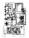
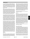
Left Turn
When a left turn is made with the engine running, the
turning of the steering wheel positions the steering con-
trol valve spool so that the load sense flow is blocked off.
Without load sense flow, pressures on t he ends of man-
ifold compensator valve (EC) start to equalize causing
(EC) to movetoward its neutral position which allows the
needed oil flow to the steering control valve. Oil is routed
out manifold port CF, into steering valve port P, through
the steering control spool, is drawn through the rotary
meter section and out the L port to the steering cylinder.
Pressure retracts the steering cylinder for aleft turn. The
rotary meter ensures that the oil flow to the cylinder is
proportional to the amount of the turning on the steering
wheel. Fluid leaving the cylinder flows back through the
steering valve R port, the spool valve, out the T port and
then returns to the hydraulic reservoir.
The steering control valve returns to the neutral position
when turning is completed.
Steering Relief Operation
When the steering cylinder reaches the end of its stroke
or if a rear wheel should encounter an obstruction (e.g.
a curb) while steering, the pressure in the steering circuit
will rise. Relief valve (RV1) in the combination manifold
senses this pressure increase. When steering circuit
pressure builds to approximately 1350 PSI (93 bar), re-
lief valve (RV1) opens and allows hydraulic flow to return
to the hydraulic reservoir. This action causes flow
across the relief valve side orifice of compensator valve
(EC) which shifts the spool in (EC) to send o il away from
the steering circuit to the fan motor circuit. Relief valve
(RV1) controls the action of compensator valve (EC)
and allows the compensator valve to divert only enough
oil flow to the steering circuit to maintain relief pressure.
Hydraulic
System