


Groundsmaster 4100--D/4110--D Hydraulic SystemPage 4 -- 131
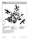
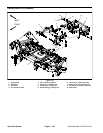
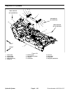
Removal (Fig. 102)
1. Park machine on a level surface, lower cutting deck,
stop engine, engage parking brake and remove key
from the ignition switch.
2. Read the General Precautions for Removing and
Installing Hydraulic System Components at the begin-
ning of this section.
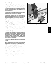
3. To prevent contamination of hydraulic system during
lift cylinder removal, thoroughly clean exterior of cylin-
der and fittings.
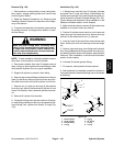
WARNING
Make sure that cutting deck (including wing
decks) is fully lowered before loosening hydrau-
lic lines from lift cylinders. If deck sections are
not fully lowered as hydraulic lines are loosened,
deck may drop unexpectedly.
NOTE: To ease installation, label the hydraulic hosesto
show their correct position on the lift cylinder.
4. Disconnect hydraulic lin es from lift cylinder and put
caps or plugs on open hydraulic lines and fittings. Label
disconnected hydraulic lines for proper installation.
5. Support lift cylinder to prevent it from falling.
6. Remove cap screw and flange nut that secure the pin
(item 5) to the liftarm. Remove pin from liftarm and cylin-
der shaft clevis which will free lift cylinder from lift arm.
7. Remove one (1) cotter pin and two (2) flat washers
from clevis pin ( item 9) that secures lift cylinder to front
frame. Pull clevis pin from frame and cylinder barrel cle-
vis.
8. Remove lift cylinder from machine.
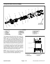
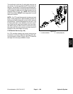
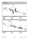
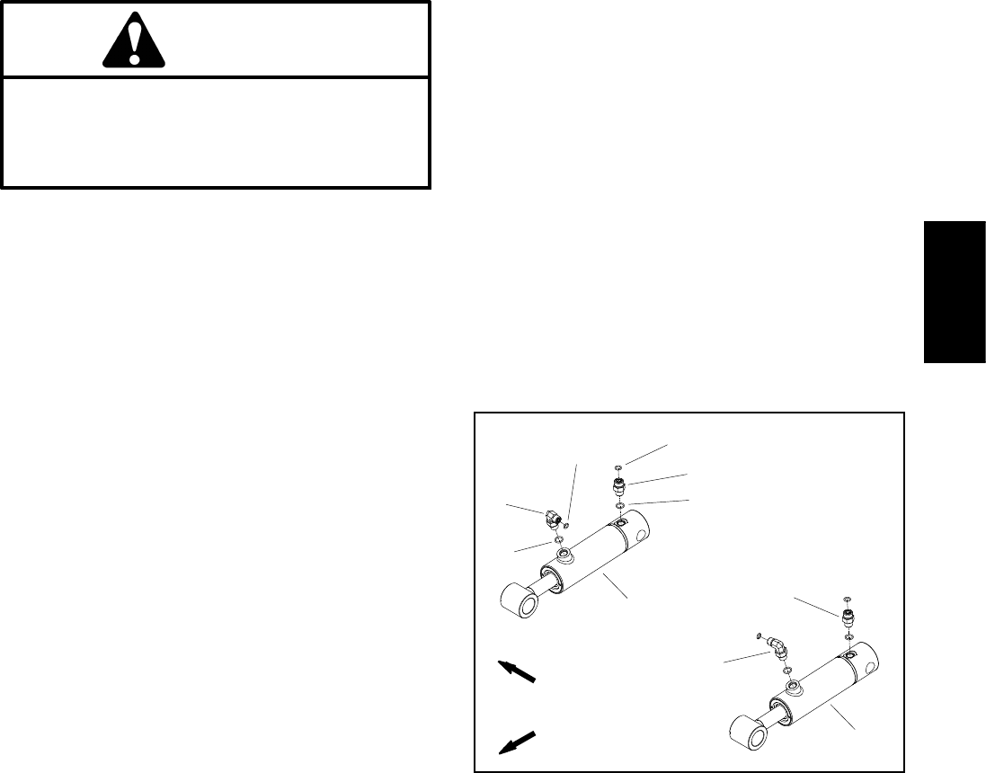
9. If hydraulic fittings are to be removed from lift cylind-
er, mark fitting orientation to allow correct assembly. Re-
move fittings from cylinder and discard O--rings (Fig.
103).
Installation (Fig. 102)
1. If fittings were removed from lift cylinder, lubricate
and place new O--rings onto fittings. Install fittings into
cylinder port openings using marks made during the re-
moval process to properly orientate fittings (Fig. 103).
Tighten fittings (see Hydraulic Fitting Installation in the
General Information section of this chapter).
2. Make sure that cotter pin and t wo (2) flat washers are
installed on one end of clevis pin (item 9).
3. Position lift cylinder barrel clevis to front frame and
insert clevis pin into frame and clevis. Secure clevis pin
with two (2) flat washers and one (1) cotter pin.
4. Insert pin (item 5) through lift arm and cylinder shaft
clevis. Secure pin to lift arm with cap screw and flange
nut.
5. Remove caps and plugs from fittings and hydraulic
lines. Using labels placed during cylinder removal, prop-
erly attach hydraulic hoses to lift cylinder (see Hydraulic
Hose and Tube Installation in the General Information
section of this chapter).
6. Lubricate lift cylinder grease fittings.
7. Fill reservoir with hydraulic fluid as r equired.
8. After assembly is completed, operate lift cylinders to
verify that hydraulic hoses and fittings are not contacted
by anything.
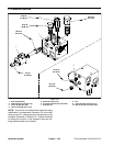
1. RH lift cylinder
2. LH lift cylinder
3. Straight fitting
4. O--ring
5. O--ring
6. 90
o
fitting
7. O--ring
8. O--ring
Figure 103
2
3
6
8
1
5
7
4
3
6
FRONT
RIGHT
Hydraulic
System