


Groundsmaster 4100--D/4110--DPage 5 -- 62Electrical System
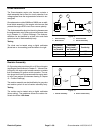
Wing Deck Position Switches
Two (2) wing deck position switches are used on the
Groundsmaster 4100--D and 4110--D as inputs for the
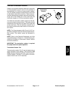
TEC controller. The position switches are powered prox-
imity switches that are normally open. The switches in-
corporate an internal reed switch and a LED. These
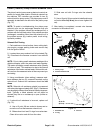
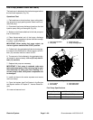
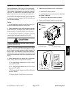
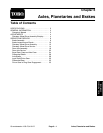
switches are secured to the center section of the cutting
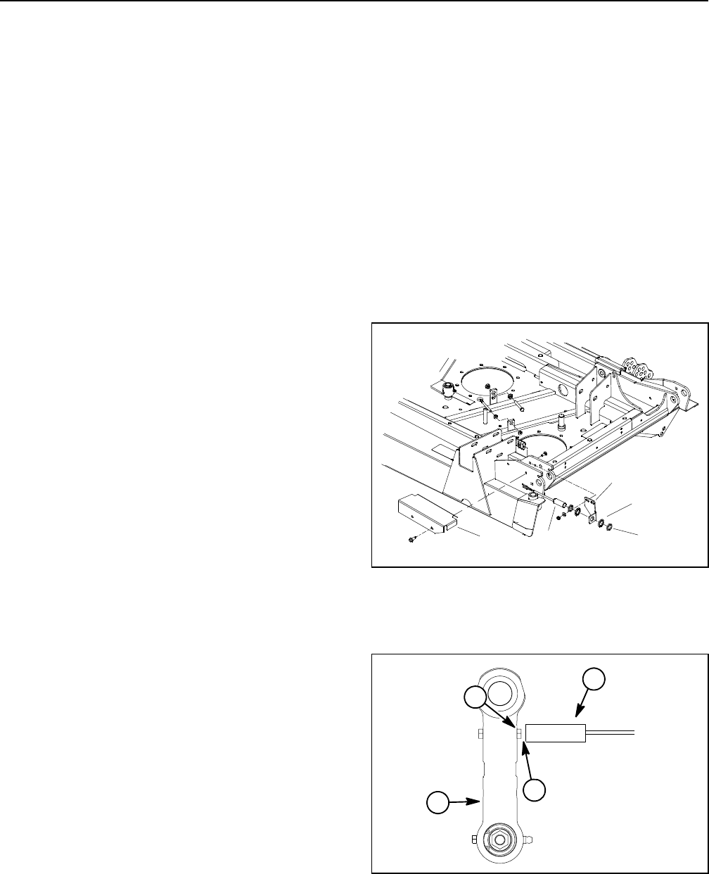
deck (Fig. 83). A bolt head on the wing deck link is the
sensing plate for the position switch (Fig. 84).
When a wing deck is lowered, the bolt head on the wing
deck link is positioned close to the position switch caus-
ing the switch to close. The closed switch provides an
input for the TEC controller t o allowwing deck operation.
When a wing deck is raised, the bolt head on the wing
deck link is moved away from the position switch so the
switch is in its normally open state. The open position
switch prevents wing deck operation when the wing
deck is raised.
Testing
1. Before disconnecting a wing deck position switch for
testing, the switch and its circuit wiring should be tested
as a TEC input with the InfoCenter Display (see In-
foCenter Display in this chapter). If the InfoCenter veri-
fies that the deck position switch and circuit wiring are
functioning correctly, no further switch testing is neces-
sary. If, however, the InfoCenter determines that the
deck position switch and circuit wiring are not function-
ing correctly, proceed with test.
2. Park machine on a level surface, lower cutting deck
(including wing decks), stop engine and apply parking
brake. Remove switch cover from deck to allow access
to switch that requires testing (Fig. 83).
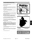
3. Turn ignition switch to the ON position (do not start
engine) and check LED on cable end of position
switches. LED should be illuminated when the wing
decks are fully lowered.
4. Start engine, fully raise wing decks and then stop en-
gine. Then, turn ignition switchto theON position (do not
start engine) and check LED on cable end of position
switches. LED should not be illuminated when the wing
decks are fully raised.
5. Lower wing decks and then stop engine.
6. If a position switch LED did not function correctly:
A. Make sure that ignition switch is OFF and discon-
nect the switch connector from deck wire harness.
B. Using a multimeter, verify that wire harness con-
nector terminal for pink wire has 12 VDC when the
ignition switch is ON.
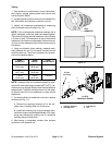
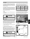
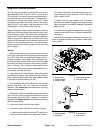
C. Make sure that gap between end of position
switch and bolt head on wing deck link when the wing
deck is lowered is from 0.070” to 0.130” (1.8 to 3.3
mm) (Fig. 84).
D. If pink wire has system voltage present and gap is
correct but switch LED did not function, replace posi-
tion switch.
7. After testing is complete, make sure that switch con-
nector is plugged into deck wire harness. Install switch
cover to deck.
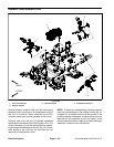
1. Switch cover
2. Position switch
3. Switch bracket
4. Lock washer (2 used)
5. Jam nut (2 used)
Figure 83
1
2
3
4
5
1. Position switch
2. Bolt head
3. Wing deck link
4. Gap location
Figure 84
1
2
3
4