


Groundsmaster 4100--D/4110--DPage 5 -- 50Electrical System
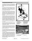
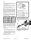
Toro Electronic Controllers (TEC)
Groundsmaster 4100--D and 4110--D machines use two
(2) ToroElectronic Controllers (TEC) to control electrical
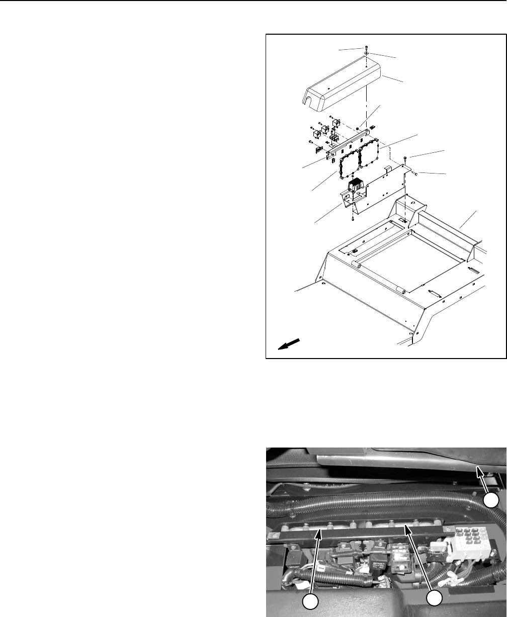
system operation. The controllers are a ttached to the
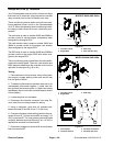
operator platform under the controller cover (Figs. 63
and 64).
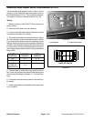
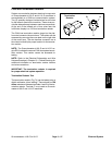
Logic power is provided to the controllers as long as the
battery cables are connected to the battery. A pair of 2
Amp fuses (fuse D--1 for the front controller and fuse
D--2 for the rear controller) provide circuit protection for
this logic power to the controllers.
The front TEC controller monitors the states of the fol-
lowing components as inputs: ignition switch, traction
pedal position sensor, parking brake switch, HI/LOW
speed switch, service brake switches, seat switch, en-
gine speed switch, hydraulic temperature sender, turn
signal switch (if equipped) and hazard switch (if
equipped).
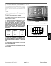
The front TEC controller controls electrical output to the
engine ECU (start and run functions), fan drive solenoid
coils (direction and flow source), traction (piston) pump
solenoids (forward and reverse) and traction solenoid
coil (HI/LOW speed). Additionally, electrical o utputs for
brake lights, turn lights and warning lights on Grounds-
master 4110--D machines are provided by the front TEC
controller. Circuit protection for front TEC outputs is pro-
vided by three (3) 7.5 Amp fuses (fuse locations A--1,
B--1 and C--1).
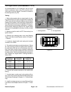
The rear TEC controller monitors the states of the fol-
lowing components a s inputs: ignition switch, cutting
deck lift switches, PTO switch, cruise control switch and
wing deck position switches.
The rear TEC controller controls electrical output to the
PTO solenoid coils, lift/lower solenoid coils and fan drive
solenoid coil (speed). Circuit protection for rear TEC
outputs is provided by three (3) 7.5 Amp fuses (fuse loc-
ations A--2, B--2 and C--2).
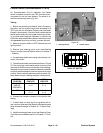
The InfoCenter display should be used to check inputs
and outputs of the TEC controllers. Information on using
the InfoCenter is included in the InfoCenter Display sec-
tion of this chapter.
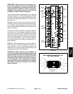
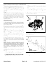
The diagram in Figure 65 depicts the connection termi-
nal functions for the TEC controllers. Note that electrical
power for controller outputs is p rovided through three (3)
connectors (PWR 2, PWR 3 and PWR 4) eachprotected
with a 7.5 amp fuse. A fifty (50) pin wire harness connec-
tor attaches to the controller. The connector pins are
identified in the diagram in Figure 65. The layout of the
wire harness connectors that plug into the TEC control-
lersisshowninFig.66.
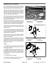
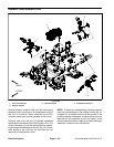
1. Controller cover
2. Screw (2 used)
3. Flat washer (2 used)
4. Flange screw (2 used)
5. Power mount
6. Relay mount
7. Carriage screw (8 used)
8. Flange nut (8 used)
9. Front TEC controller
10. Rear TEC controller
11. Operator platform
Figure 63
FRONT
2
3
7
1
6
4
5
8
9
10
11
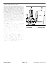
1. Front TEC controller
2. Rear TEC controller
3. Operator seat
Figure 64
2
1
3