


Groundsmaster 4100--D/4110--D Hydraulic SystemPage 4 -- 65
The cooling fan circuit test should be performed to make
sure that the engine cooling fan circuit has the correct
system pressure and fan speed.
Procedure for Engine Cooling Fan Circuit
Test
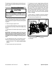
CAUTION
Prevent personal injury and/or damage to equip-
ment. Read all WARNINGS, CAUTIONS and Pre-
cautions for Hydraulic Testing at the beginning
of this section.
1. Park machine on a level surface with the cutting deck
lowered and off. Make sure hydraulic oil is at normal op-
erating temperature, engine is off and the parking brake
is applied.
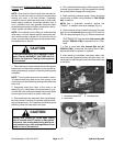
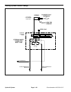
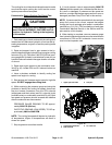
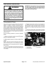
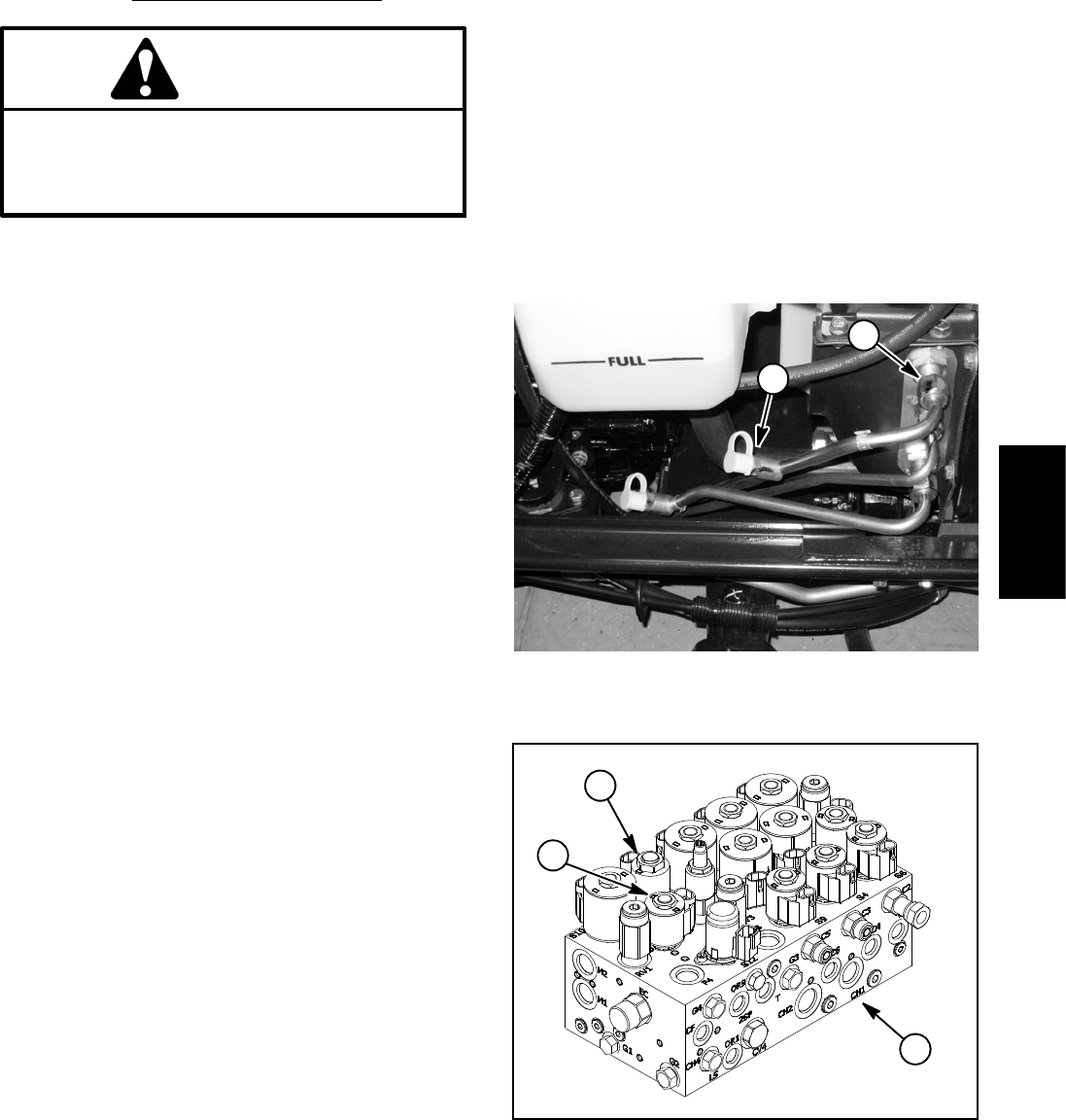
2. Raiseandsupporthoodtogainaccesstothehy-
draulic tubes that supply hydraulic flow to engine cooling
fan motor (Fig. 45). Connect a 5,000 PSI (345 bar) pres-
sure gauge with hydraulic hose attached to test port on
hydraulic tube connected inthe upper location on radiat-
or shroud.
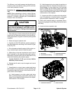
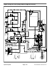
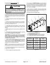
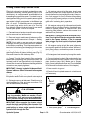
3. Raise seat t o gain access to the combination man-
ifold (Fig. 46). Locate PRV and S11 solenoid valves on
manifold.
4. Have a phototac available to identify cooling fan
speed once engine is running.
5. Start engine and increase engine speed to high idle
speed. DO NOT engage the cutting deck.
6. While monitoring the pressure gauge and using the
phototac to identify the cooling fan speed, disconnect
the wire harness connectors from the PRV solenoid
(white/green and black wires) and S11 solenoid (violet
and black wires) on combination manifold (Fig. 46). Both
fan speed and pressure should increase and stabilize
after the solenoids are disconnected.
PRESSURE GAUGE READING TO BE approxi-
mately 3250 PSI (224 bar).
PHOTOTAC READING (FAN SPEED) TO BE ap-
proximately 2800 to 3000 RPM.
NOTE: The cooling fan speed will depend on hydraulic
oil temperature. Higher oil temperatures will result in
slower fan speed.
7. Stop engine and record test results.
8. If circuit pressure rises to approximately 3250 PSI
(224 bar) but fan speed is low, consider that the fan mo-
tor is worn or damaged. If pressure and fan speed are
both low, consider that the gear pump section is worn or
damaged (see Gear Pump Flow Test in this section).
NOTE: If pressure and fan speed are both low and gear
pump flow proves to be correct, suspect that engine
cooling fan circuit cartridge valve seals in combination
manifold(e.g.S10,S11,PRV)areleakingorfaulty(see
Combination Manifold Service in the Service and Re-
pairs section of this chapter).
9. When testing is complete, remove pressure gauge
from hydraulic tube test port and reconnect wire harness
connectors to PRV and S11 solenoids. Lower and se-
cure hood and operator seat.
1. Upper hydraulic tube 2. Test port
Figure 45
1
2
1. Combination manifold
2. PRV solenoid
3. S11 solenoid
Figure 46
1
2
3
Hydraulic
System