


Groundsmaster 4100--D/4110--D Hydraulic SystemPage 4 -- 75
NOTE: The operator platform needs to be raised from
the main frame so that the hydraulic reservoir can be re-
moved from the machine (see Operator Platform in the
Service and Repairs section of Chapter 6 -- Chassis).
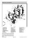
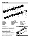
Removal (Fig. 52)
1. Park machine on a level surface, lower cutting deck,
stop engine, apply parking brake and remove key from
the ignition switch.
2. Read the General Precautions for Removing and
Installing Hydraulic System Components at the begin-
ning of the Service and Repairs section of this chapter.
3. Drain reservoir into a suitable container.
IMPORTANT: Follow all local codes and regulations
when recycling or disposing hydraulic fluid.
IMPORTANT: Make sure to not damage the electric-
al wire harness, hydraulic hoses or other compo-
nents while raising the operator platform.
4. Raise and support operator platform from the main
frame to allow clearance to remove the hydraulic reser-
voir from the machine (see Operator Platform in the Ser-
vice and Repairs section of Chapter 6 -- Chassis).
5. Disconnect hydraulic hoses from reservoir. Label
disconnected hydraulic hoses for proper installation.
Put plugs on open hydraulic hoses and reservoir fittings
to prevent contamination.
6. Loosen hose clamp (item 24) that secures suction
hose to tank strainer. Remove suction hose (item 25)
from strainer.
7. Remove tank strainer (item 14) from reservoir.
8. Remove cap screw (item 22) and flat washer (item
21) that secure tank mount (item 19) to left side of frame.
9. Carefully remove hydraulic reservoir and tank mount
assembly (items 3, 15, 16, 17, 18 and 19) from machine.
Inspection
1. Clean hydraulic reservoir and tank strainer with sol-
vent.
2. Inspect reservoir for leaks, cracks or other damage.
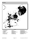
Installation (Fig. 52)
NOTE: Make sure that recess bumper (item 3) and thin
spacer (item 4) are secured to right side of frame before
hydraulic reservoir is installed to m achine.
1. Position hydraulic reservoir to machine. Make sure
that recess bumper (item 3) on right side of frame is in-
serted into tank slot.
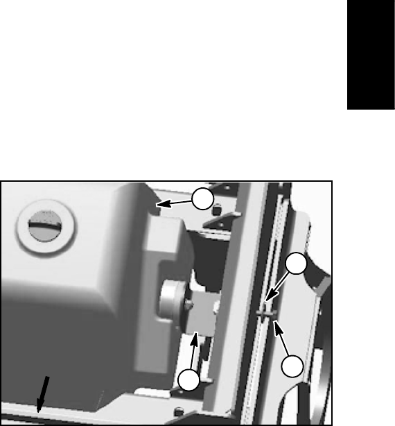
2. Slide t ank mount assembly (items 15, 16, 3, 17, 18
and 19) between frame and hydraulic tank and position
bumper into slot on left side of reservoir. Align tank
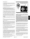
mount with hole in frame. Secure mount with cap screw
and flat washer (Fig. 53).
3. Install tank strainer into reservoir port and torque
from 80 to 88 ft--lb (109 to 119 N--m).
4. Remove plugs from hydraulic hoses and reservoir fit-
tings that were placed during the removal process. Us-
ing labels placed during reservoir removal, connect
hydraulic hoses to fittings on reservoir. Secure hoses
with hose clamps.
IMPORTANT: Make sure to not damage the electric-
al wire harness, hydraulic hoses or other compo-
nents while lowering the operator platform.
5. Carefully lower operator platform to the main frame
(see Operator Platform in the Service and Repairs sec-
tion of Chapter 6 -- Chassis). Make sure that fasteners
are properly torqued during assembly.
IMPORTANT: Use on ly hydraulic fluids specified in
Operator’sManual. Other fluids could causesystem
damage.
6. Fill reservoir with new hydraulic oil to proper level.
7. Properly fill hydraulic system (see Charge Hydraulic
System in this section).
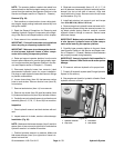
8. Stop engine and check for hydraulic oil leaks. Check
hydraulic reservoir oil level.
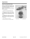
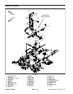
1. Hydraulic reservoir
2. Cap screw
3. Flat washer
4. Tank mount
Figure 53
FRONT
1
2
3
4
Hydraulic
System