


Groundsmaster 4100--D/4110--D Hydraulic SystemPage 4 -- 17
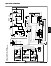
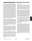
Raise Cutting Deck
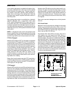
A four section gear pump is coupled to the piston (trac-
tion) pump. The third gear pump section supplies hy-
draulic flow to the lift/lower circuit, the engine cooling fan
circuit and the traction charge circuit.
Each of the cutting deck sections (main, right wing and
left wing) can be raised independently with the use of
three (3) switches on the armrest console. Pressing the
rear of a lift switch provides an input for the TEC control-
ler to raise the cutting deck or wing deck. The controller
provides electrical outputs to solenoids in the combina-
tion control manifold to allow appropriate manifold valve
shift that causes a cutting deck to raise.
A relief valve (RV2) located in the combination control
manifold limits lift/lower circuit pressure to 2500 PSI
(172 bar). An adjustable pressure relieving valve (PR)
in the combination manifold maintains back pressure
(counterbalance) on the deck lift cylinders to allow some
of the cutting deck weight to be transferred to the traction
unit to improve traction.
When the lift/lower circuit is not being used (all lift
switches in the neutral position), solenoid valve S1 in the
combination manifold is not energized and gear pump
section oil flow is directed toward the engine cooling fan
motor.
NOTE: To raise a cutting deck, the operator must be in
the operator seat.
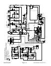
Raise Center Cutting Deck
To raise the cutting deck, the rear of the center console
liftswitchisdepressed.Theswitchsignalisaninputto
the TEC controller which p rovides an electrical output to
solenoid valves S1 and S5 in the combination manifold.
The energized solenoid valves shift to allow a passage
for circuit oil flow to the barrel end of the cutting deck lift
cylinders. Shifted S1 allows gear pump section oil flow
to be available for the lift/lower circuits. Shifted S5 allows
an oil path to the barrel end of the front lift cylinders caus-
ing the lift cylinders to extend and raise the cutting deck.
Check orifice OR5 under the fitting in manifold port C2
allows oil flow to bypass the orifice when the deck is rais-
ing. An orifice in manifold port OR4 (.040) exists to con-
trol the raise speed of the cutting deck.
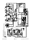
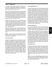
Raise Right Wing Deck
To raise the right wing deck, the rear of the right console
lift switch is depressed as an input to the TEC controller.
The controller provides an electrical output to solenoid
valves S1, S7 and S9 in the combination manifold. The
energized solenoid valves shift to allow a passage for
circuit oil flow to the barrel end of the right wing deck lift
cylinder. Shifted S1 allows gear pump section oil flow to
be available for the lift/lower circuits. Shifted S7 and S9
allow an oil path to the barrel end of the right lift cylinder
to extend the lift cylinder and raise the right wing deck.
Orifice OR6 (.063) controls the raising of the wing deck.
Check orifice OR7 is bypassed when raising the right
wing deck. Oil from the extending cylinder is directed
through S8 (de--energized), to the oil filter and then to
thetractionchargecircuit.
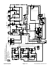
Raise Left Wing Deck
To raise the left wing deck, the rear of the left console lift
switch is depressed as an input to the TEC controller.
The controller provides an electrical output to solenoid
valves S1, S2 and S4 in the combination manifold. The
energized solenoid valves shift to allow a passage for
circuit oil flow to the barrel end of the left wing deck lift
cylinder. Shifted S1 allows gear pump section oil flow to
be available for the lift/lower circuits. Shifted S2 and S4
allow an oil path to the barrel end of the right lift cylinder
to extend the lift cylinder and raise the right wing deck.
Orifice OR2 (.063) controls the raising of the wing deck.
Check orifice OR3 is bypassed when raising the left
wing deck. Oil from the extending cylinder is directed
through S3 (de--energized), to the oil filter and then to
thetractionchargecircuit.
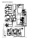
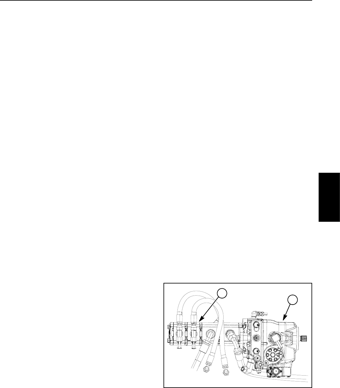
1. Piston (traction) pump 2. 3
rd
gear pump section
Figure 10
2
1
Hydraulic
System