


Groundsmaster 4100--D/4110--DPage 5 -- 4Electrical System
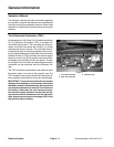
CAN--bus Communications
The two (2) TEC controllers, the Yanmar engine elec-
tronic control unit and the InfoCenter Display used on
the Groundsmaster 4100--D and 4110--D communicate
with each other on a CAN-- bus system. Using this sys-
tem allows the traction unit to fully integrate all the differ-
ent electrical components of the tractor and bring them
together as one. The CAN--bus system reduces the
number of electrical components and connections used
on the machine and allows the number of wires in the
wire harness to be significantly reduced. The integration
of electrical functions also allows the InfoCenter Display
to assist with electrical system diagnostics.
CAN identifies the Controller Area Network that is used
between the controllers on the Groundsmaster. Two (2)
specially designed, twisted wires form the bus. These
wires provide the data pathways between the control-
lers (the TEC controllers and the Yanmar electronic con-
trol unit) and the InfoCenter Display used on the
machine. The engineering term for these wires are CAN
High and CAN Low. At the ends of the twisted pair of bus
wires are 120 ohm termination resistors. One of these
resistors is included in the wire harness and the second
is inside the engine ECU.
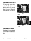
Each of the components that is controlled by the CAN--
bus link needs only four (4) wires to operate and commu-
nicate to the system: CAN High, CAN Low, B+ (power)
and g round. The CAN--bus needs the ignition switch ON
input for both the TEC and engine ECU to be activated.
Electrical Drawings
The electrical schematics and wire harness drawings for
Groundsmaster 4100--D and 4110--D machines are lo-
cated in Chapter 10 -- Foldout Drawings.