


Groundsmaster 4100--D/4110--D Hydraulic SystemPage 4 -- 55
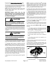
The PTO circuit relief pressure test should be performed
to make sure that the PTO circuit r elief pressures are
correct.
Procedure for PTO Relief Pressure
Test
CAUTION
Prevent personal injury and/or damage to equip-
ment. Read all WARNINGS, CAUTIONS and Pre-
cautions for Hydraulic Testing at the beginning
of this section.
1. Park machine on a level surface with the cutting deck
lowered and off. Make sure hydraulic oil is at normal op-
erating temperature, engine is off and the parking brake
is applied.
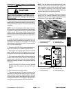
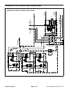
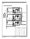
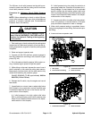
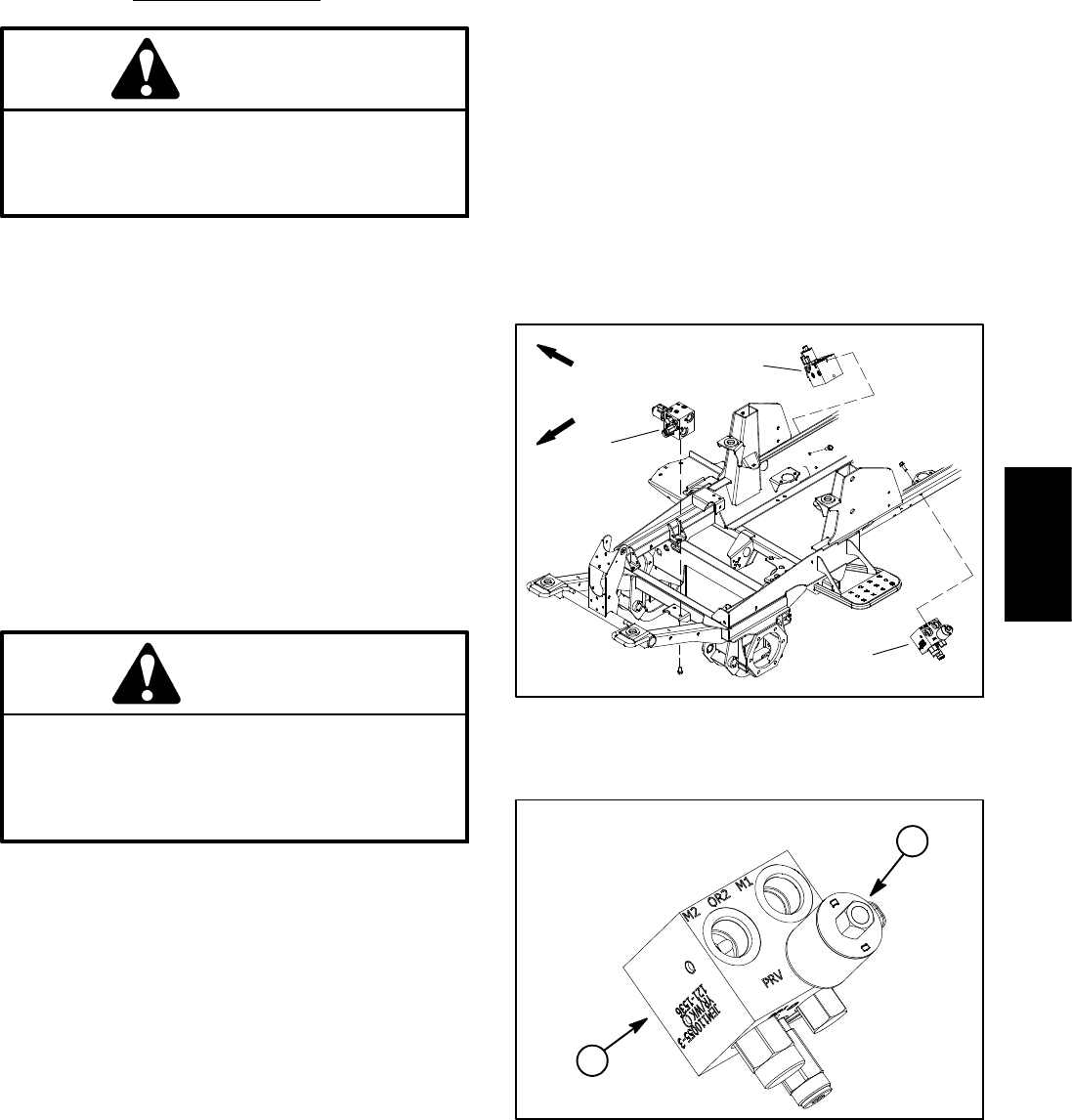
2. Locate PTO (deck) manifold to be tested (Fig. 38).
Disconnect hydraulic hose at PTO manifold port (M1).
NOTE: An alternative to using manifoldport (M1) would
be to disconnect the inlet hydraulic hose to the deck mo-
tor.
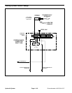
3. Install tester (flow and pressure) in series with the
disconnected hose and PTO manifold port ( M1) (or mo-
tor inlet if hose was disconnected at deck motor). Make
sure the flow control valve on tester is fully open.
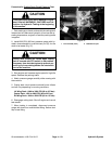
CAUTION
Cutting deck blades will rotate when cutting
deck is lowered with PTO switch in ON position.
Keep away from cutting deck during test to pre-
vent personal injury from rotating blades. Do not
stand in front of the machine.
4. Start engine and increase engine speed to high idle
speed. Release the parking brake.
5. Watch pressure gauge carefully while slowly closing
the tester f low control valve to fully closed.
6. As the PTO relief valve lifts, system pressure should
be approximately:
2900 to 3100 PSI (200 to 213 bar) for the center and
left wing decks
1900 to 2100 PSI (131 to 144 bar) for the right wing
deck
7. Fully open tester flow control valve and disengage
cutting deck. Shut off engine and record test results.
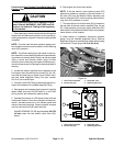
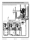
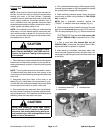
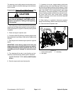
8. If relief pressure is incorrect, remove PRV valve on
mow manifold and clean or replace valve (see PTO
Manifold Service in the Service and Repairs section of
this chapter). Also, if pressure is still low after PRV valve
service, check for restriction in pump intake line. The
front gear pump section(center cuttingdeck circuit)and/
or the second gear pump section (side cutting deck cir-
cuits) could also be suspected of wear, damage or
inefficiency (see Gear Pump Flow Test in this section).
9. When relief pressure testing is complete, disconnect
tester from PTO manifold and hydraulic hose. Recon-
nect hydraulic hose that was disconnected for test pro-
cedure.
1. Center PTO manifold
2. LH PTO manifold
3. RH PTO manifold
Figure 38
FRONT
RIGHT
1
3
2
1. PTO manifold 2. PRV valve
Figure 39
1
2
LEFT PTO MANIFOLD SHOWN
Hydraulic
System