


Groundsmaster 4100--D/4110--D Hydraulic SystemPage 4 -- 59
The lift/lower circuit relief pressure test should be per-
formed to make sure that the cutting unit lift and lower
circuit relief pressure is correct.
Procedure for Lift/Lower Circuit Relief Pressure
Test
NOTE: Before attempting to check or adjust lift/lower
circuit relief pressure, make sure that counterbalance
pressure is correctly adjusted (see Counterbalance
Pressure Test in this section).
CAUTION
Prevent personal injury and/or damage to equip-
ment. Read all WARNINGS, CAUTIONS and Pre-
cautions for Hydraulic Testing at the beginning
of this section.
1. Park machine on a level surface with the cutting deck
lowered and off. Make sure hydraulic oil is at normal op-
erating temperature, engine is off and the parking brake
is applied.
2. Raise and support operator seat.
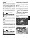
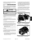
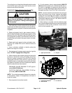
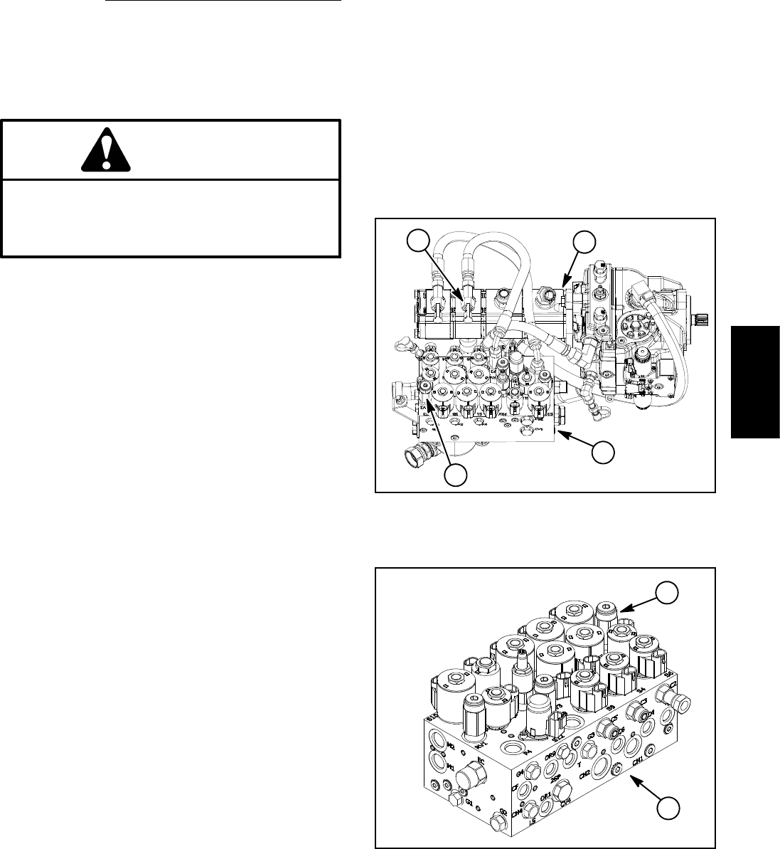
3. Connect a 5,000 PSI (345 bar) pressure gauge to
test fitting attached to tee fitting in third section of gear
pump (Fig. 42).
4. Sit on the seat and start the engine. With engine run-
ning, increase engine speed to high idle speed.
5. While sitting on the seat, depress the rear of one of
the lift switches to fully raise the cutting deck section.
Momentarily hold the switch with the deck section fully
raised while watching the pressure gauge.
GAUGE READING TO BE approximately 2450 to
2550 PSI (170 to 175 bar).
6. Release the lift switch,stoptheengineandrecord
test results.
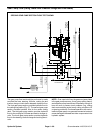
7. If specification is not met, clean or adjust relief valve
RV2 located in the combination control manifold (see
Combination Manifold Service in the Service and Re-
pairs section of this chapter).
A. If relief pressure is too high, adjust relief valve
RV2 to reduce lift/lower circuit relief pressure (see
Adjust Control Manifold Relief Valves in the Adjust-
ments section of this chapter).
B. If relief pressure is too low, check for restriction in
gear pump intake line. Check the lift cylinders for in-
ternal leakage. If pump intake line is not restricted
and lift cylinders are not leaking, adjust relief valve
RV2 to increase lift/lower circuit relief pressure (see
Adjust Control Manifold Relief Valves in the Adjust-
ments section of this chapter).
C. If pressure is still too low after relief valve adjust-
ment, lift cylinder(s) or the third section of the gear
pump should be suspected o f wear or damage.
8. When relief pressure testing is completed, discon-
nect pressure gauge f rom test fitting. Secure dust cap to
test fitting.
9. Lower and secure operator seat.
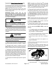
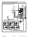
1. Gear pump
2. Third section test fitting
3. Combination manifold
4. Relief valve RV2
Figure 42
2
3
4
1
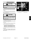
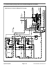
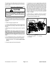
1. Combination manifold 2. Relief valve RV2
Figure 43
2
1
Hydraulic
System