


Groundsmaster 4100--D/4110--D Hydraulic SystemPage 4 -- 13
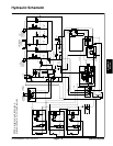
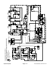
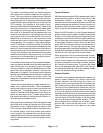
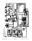
Traction Circuit: HI Speed (Transport)
The traction circuit piston pump is a variable displace-
ment pump that is directly coupled to the engine fly-
wheel. This pump utilizes an integral electro--hydraulic
servo piston assembly that controls the rate and direc-
tion of hydraulic flow. Pressing the traction pedal rotates
a potentiometer that provides an input to the machine
TEC controller. The controller in turn sends a corre-
sponding PWM (Pulse Width Modulation) output to the
electronic pump control to rotate the pump swash plate
accordingly to control pump output and direction. Trac-
tion circuit oil is directed to the dual displacement front
wheel and rear axle motors. Operating pressure on the
high pressure side of the closed traction circuit loop is
determined by the amount of load developed at the
wheel and axle motors. As the traction load increases,
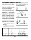
circuit pressure can increase to relief valve settings:
4350 PSI (300 bar) in forward and 5000 PSI (345 bar)
in reverse. If traction circuit pressure exceeds the relief
setting, oil flows through the piston pump relief valve to
the low pressure side of the closed loop traction circuit.
Traction circuit pressure can be measured at test ports
attached to the sides of the piston pump. The forward
traction port is on the right side of the pump and the re-
verse traction port is on the left side.
Front wheel and rear axle motors are positive displace-
ment, two speed variable motors that allow operation in
either LOW (mow) or HI (transport) speed. T he motors
are spring biased to maximum displacement for LOW
speed and are hydraulically shifted to minimum dis-
placement f or HI speed. The rear axle motor includes a
flushing valve that bleeds off a small amount of hydraulic
oil for cooling of the closed loop traction circuit. The
charge circuit replaces oil that is bled from the circuit by
theflushingvalve.
Traction circuit components use small amounts of hy-
draulic oil for internal lubrication. Fluid is designed to
leak across traction pump and motor components into
the case drain. This leakage results in the loss of hy-
draulic oil from the closed loop traction circuit that is re-
placed by the charge circuit. The gear pump sections
that supply the steering, cooling fan and lift/lower cir-
cuits also provide charge circuit oil.
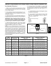
Gear pump flow for the charge circuit is directed through
the oil filter and to the low pressure side of the closed
loop traction circuit. Charge pressure is limited to 250
PSI (17 bar) by a relief valve located in the piston pump.
An optional traction circuit flow divider splits traction
pump hydraulic flow between the front wheel motors
(approximately 43%) and rear axle motor (approximate-
ly 57%) to prevent excessive circuit flow going to a spin-
ning wheel.
Forward Direction
WiththearmrestconsoleHI/LOWspeedswitchintheHI
speed (transport) position, solenoid valve (S12) in the
combination manifold is energized. The energized
solenoid valve directs charge pressure to shift the front
wheel motors and rear axle motor to their minimum dis-
placement. With the motors at their minimum displace-
ments, a higher traction speed is available for transport.
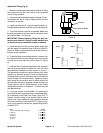
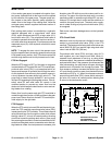
When the HI/LOW switch is in the HI speed (transport)
position and the traction pedal is pushed in the forward
direction, oil from the piston pump is directed to the front
wheel motors and rear axle motor through a parallel sys-
tem. Oil flow to the front wheel motors drives the motors
in the forward direction and then returns to the piston
pump. Oil flow to the rear axle motor drives the motor in
the forward direction. Oil returning from the axle motor
entersthereartractionmanifoldattheM8port.Flowby-
passes the PRcartridge through theCV check valve, out
manifold port P2 and returns to the piston pump.
When going down a hill, the tractor becomes an over--
running load that drives the front wheel and rear axle
motors. In this condition, the rear axle motor could lock
up as the oil pumped from the motor increases pressure
as it returns to the piston pump. To prevent rear wheel
lock up, an adjustable relief valve (RV) in the rear trac-
tion manifold reduces rear axle motor pressure created
in down hill, dynamic braking conditions.
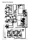
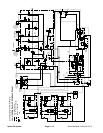
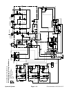
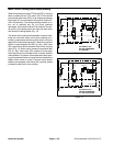
Reverse Direction
The traction circuit operates essentially the same in re-
verse HI speed (transport) as it does in the forward
direction. However, the flow through the circuit is re-
versed. Oil flow from the piston pump is directed to the
front wheel motors andalso to the rear t raction manifold.
The oil to the front wheel motors drives them in the re-
verse direction and then returns to the piston pump. The
oil to the rear traction manifold enters the rear traction
manifold at port P2 and flows through pressure reducing
valve (PR) which limits the down stream pressure to the
rear axle motor to 380 PSI (26 bar) so the rear wheels
will not scuff the turf during reverse operation. This re-
duced pressure flow is directed out rear traction mani-
fold port M8 to dr ive the rear axle motor in reverse.
Return oil from the rear motor returns to the piston
pump.
Hydraulic
System