


58
Chapter 3: Testing Performance
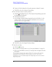
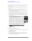
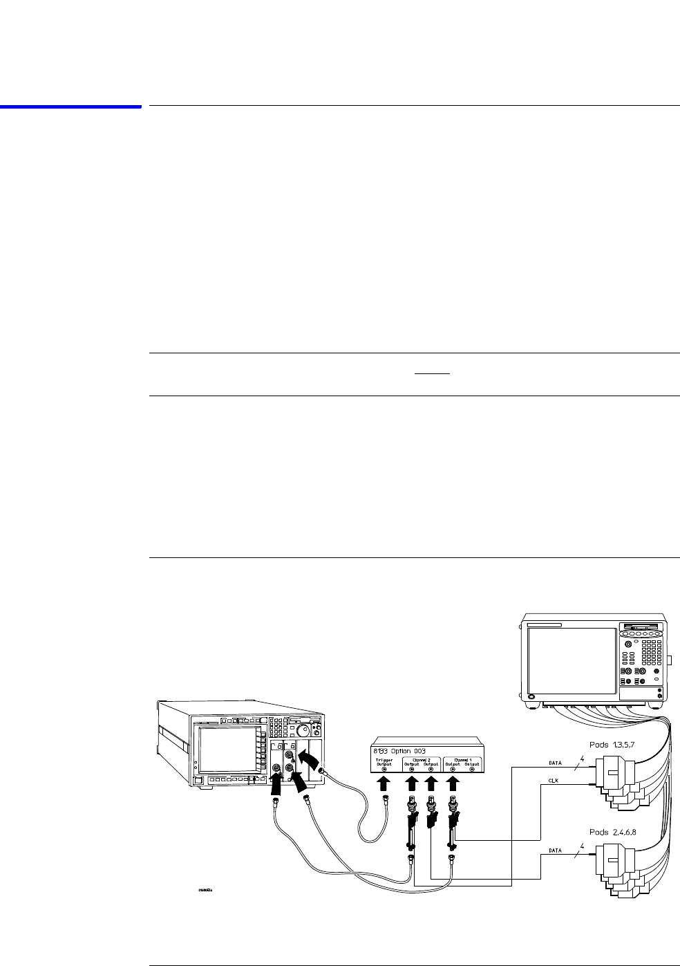
To test the single-clock, multiple-edge, state acquisition
Connect and configure the logic analyzer
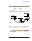
1 Using the 6-by-2 test connectors, connect the first combination of logic
analyzer clock and data channels listed in one of the following tables to the
pulse generator.
If you are testing a 1680/81/90/91A,AD, you will repeat this test for the second
combination.
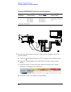
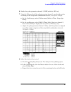
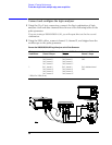
2 Using the SMA cables, connect channel 1, channel 2, and trigger from the
oscilloscope to the pulse generator.
Connect the 1680/81/90/91A,AD Logic Analyzer to the Pulse Generator
Testing
Combinations
Connect to 8133A
Channel 2 Output
Connect to 8133A Channel
2 Output
Connect to 8133A
Channel 1 Output
1 Pod 1, channel 3
Pod 3, channel 3
Pod 5, channel 3
Pod 7, channel 3
Pod 2, channel 3
Pod 4, channel 3
Pod 6, channel 3
Pod 8, channel 3 *
Pod 1 clock/data channel
(Clk1)
2 Pod 1, channel 11
Pod 3, channel 11
Pod 5, channel 11
Pod 7, channel 11
Pod 2, channel 11
Pod 4, channel 11
Pod 6, channel 11
Pod 8, channel 11 *
Pod 1 clock/data channel
(Clk1)
*1680A,AD or 1690A,AD only.