


50
Chapter 3: Testing Performance
To test the multiple-clock state acquisition
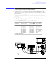
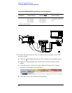
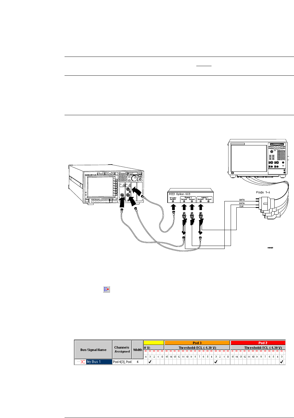
Connect the 1682/83/92/93A,AD Logic Analyzer to the Pulse Generator
3 Activate the data channels that are connected according to one of the
previous tables:
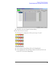
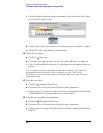
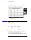
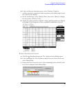
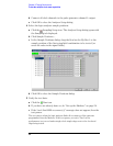
a Click the Bus/Signal Setup icon. The Analyzer Setup dialog opens.
b Under the Buses/Signals tab, click Delete All at the bottom of the
dialog.
c Using the mouse, activate the data channels being tested. Assign
channels to bus/signal name My Bus 1.
d Click OK to close the Analyzer Setup dialog.
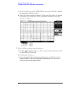
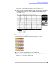
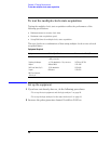
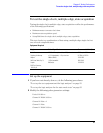
Testing
Combination
Connect to 8133A
Channel 2 Output
Connect to 8133A
Channel 2 Output
Connect to 8133A
Channel 1 Output
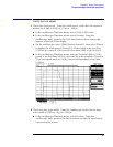
1 Pod 1, channel 3
Pod 2, channel 3
Pod 3, channel 3
Pod 4, channel 3
Pod 1, channel 11
Pod 2, channel 11
Pod 3, channel 11 *
Pod 4, channel 11 *
Clock/data channel for Pod 1,
2, 3, and 4 (Clk 1, Clk 2, Clk 3,
Clk 4)
*1682A, AD or 1692A, AD only.