


34
Chapter 3: Testing Performance
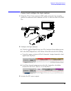
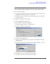
To set up the logic analyzer for the state mode tests
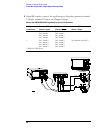
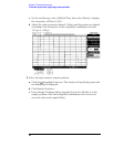
3 Configure the trigger according to your logic analyzer:
a In the Listing window, click on the trigger pattern field for My Bus 1 to
select.
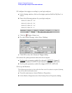
b Enter the following pattern for your logic analyzer.
1680A,AD, 1690A,AD - "AA"
1681A,AD, 1691A,AD - "2A"
1682A,AD, 1692A,AD - "AA"
1683A,AD, 1693A,AD - "A"
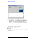
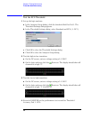
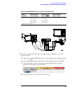
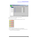
c Click the Trigger Setup icon.
d For the Default Storage, select Store Nothing.
e Click OK to close the Advanced Trigger dialog.
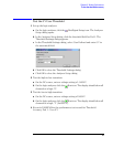
4 Activate the pulse generator data and clock outputs:
a On the pulse generator, enable the channel 1 OUTPUT, channel 1
OUTPUT
, channel 2 OUTPUT and channel 2 OUTPUT (LEDs off)
b On the pulse generator, enable the trigger OUTPUT. (LED off)
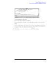
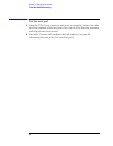
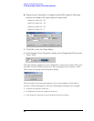
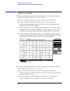
5 Set up the Markers:
The following procedure is done after the first run of test data is acquired (during
one of the state clock mode tests).
a From the main menu, choose Markers>Properties....
b In the Marker Properties tab of the Listing Viewer Properties dialog,