


108
Chapter 5: Troubleshooting
General Troubleshooting
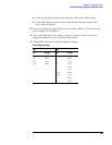
2 Set up the pulse generator according to the following table.
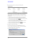
Pulse Generator Setup
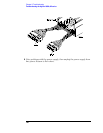
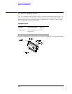
3 Using four 6-by-2 test connectors, four BNC Couplers, and four SMA (m) -
BNC (f) Adapters, connect the logic analyzer to the pulse generator
channel outputs (to make the test connectors, see chapter 3, "Testing
Performance"):
a Connect the even-numbered channels of the lower byte of the pod
under test and Clk 1 to the pulse generator channel 1 OUTPUT.
b Connect the odd-numbered channels of the lower byte of the pod under
test to the pulse generator channel 1 OUTPUT.
c Connect the even-numbered channels of the upper byte of the pod
under test to the pulse generator channel 2 OUTPUT.
d Connect the odd-numbered channels of the upper byte of the pod
under test to the pulse generator channel 2 OUTPUT.
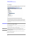
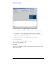
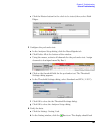
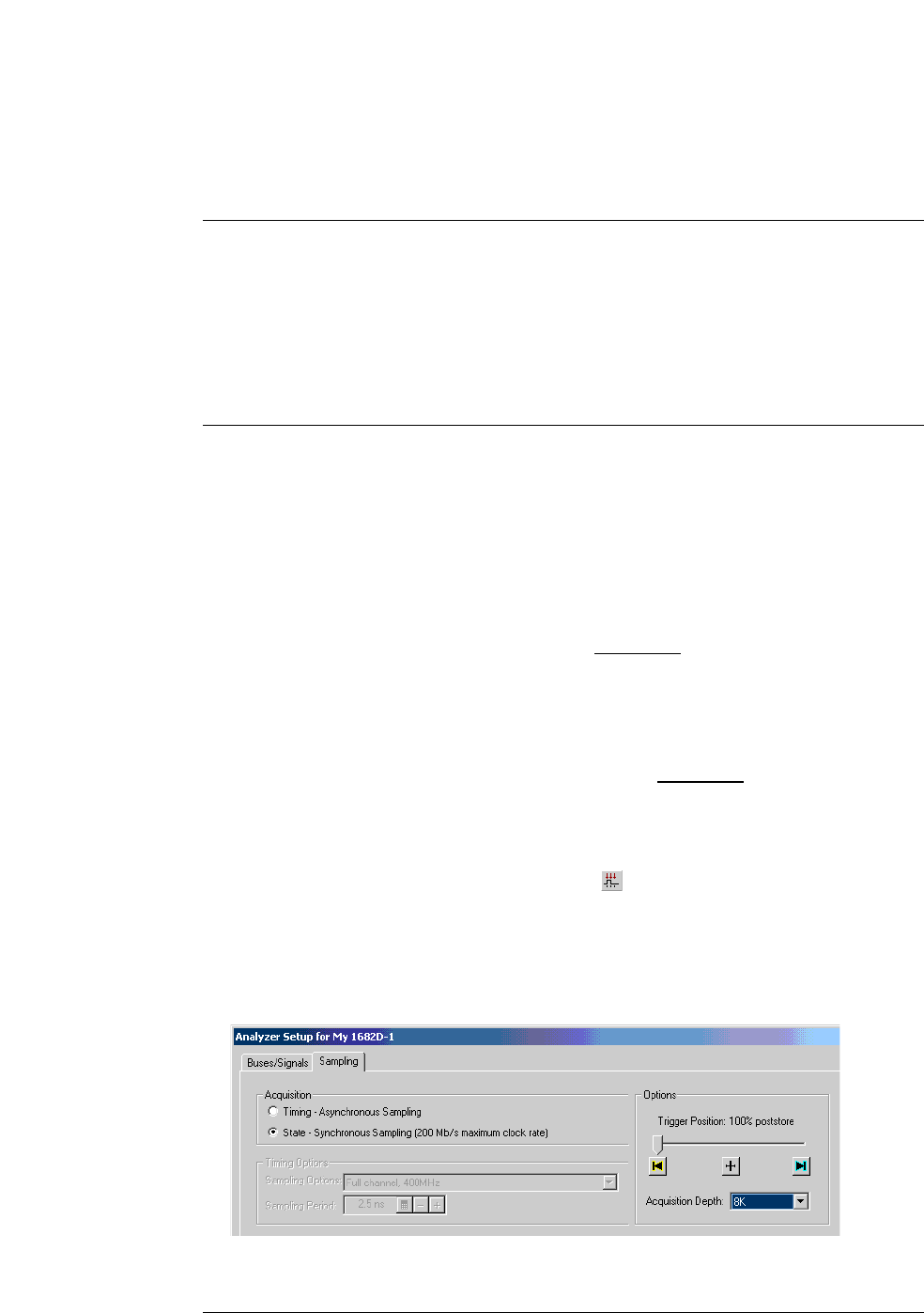
4 Configure the Analyzer Setup dialog:
a In the Waveform window, click on the Sampling Setup icon.
b In the Analyzer Setup dialog, select State - Synchronous Sampling.
c Configure Trigger Position - 100% poststore.
d Select an Acquisition Depth of 8K.
Timebase Channel 2 Trigger Channel 1
Mode: Int Mode: Pulse Divide: Divide 1 Mode: Square
Period: 20.000 ns Divide: Square ÷ 1 Ampl: 0.50 V Delay: 0.000 ns
Offs: 0.00 V
Ampl: 0.80 V Ampl: 0.80 V
Offs: -1.30 V Offs: -1.30 V
COMP: Disabled (LED Off) COMP: Disabled (LED Off)