


107
Chapter 5: Troubleshooting
General Troubleshooting
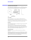
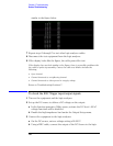
LED #1 (closest to the red LED) - the on-board processor is properly initialized and
running, attempting to load the IEEE 1394 link layer configuration
LED #2 - the IEEE 1394 link layer is loaded and configured
LED #3 - the IEEE 1394 is loaded, properly configured, and is running
A blinking green LED signifies a failure of one of the above steps. In this case, the
acquisition board must be replaced.
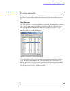
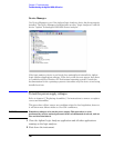
When the IEEE 1394 port on the acquisition board is configured and initialized,
the agLogicSvc service running on the Windows XP Professional operating system
senses the acquisition board. The agLogicSvc service then loads configuration
code into the interface FPGA on the acquisition board. When the FPGA is
configured, the red LED is turned off. The acquisition board is then properly
configured and initialized both to communicate with the system processor and to
acquire data.
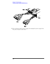
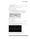
To test the logic analyzer probe cables
This test allows you to functionally verify the probe cable and probe tip assembly
of any of the logic analyzer pods. Only one probe cable can be tested at a time.
Repeat this test for each probe cable to be tested.
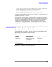
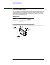
Equipment Required
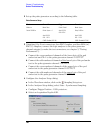
1 Turn on the equipment and the logic analyzer.
Equipment Critical Specification
Recommended
Model/Part
Pulse Generator 200 MHz, 2.5 ns pulse width,
<600 ps rise time
8133A Option 003
Adapter (Qty 4) SMA (m) - BNC (f) 1250-1200
Coupler (Qty 4) BNC (m)(m) 1250-0216
6x2 Test Connectors (Qty 4)